Lesson Contents
The Virtual Switching System (VSS) allows two Cisco Catalyst 6500 or 4500 chassis to bond together so that is seen as a single virtual switch to the rest of the network. Other devices will see the VSS configured 6500 as a single device which means it’s possible to use multi-chassis etherchannel and protocols like spanning tree will only see a single switch.
Some other features are NSF (Non-Stop Forwarding) / SSO (Stateful Switchover), which means that when a single chassis fails, the other one will take over without any downtime since the routing table / CEF table, etc. are stored in both chassis’ supervisors.
Another cool feature is EFSU (Enhanced Fast Software Upgrade) which allows you to upgrade the IOS version without any downtime.
In this lesson, I will be using two Cisco Catalyst 6504 switches with 720-10G VSS supervisors to show you how to configure VSS and verify that it’s working.
Right now, I have two 6500s that are running in “standalone”. In order to bond these two using VSS, we will have to do the following:
- Configure a virtual switch domain on both switches and configure one switch as “switch 1” and the other one as “switch 2”.
- Configure the virtual switch links.
- Execute the conversion command, which will reboot the switches.
Before we configure anything let’s verify what modules my 6500s have and see if they are running the same IOS or not!
Verification
We should start by taking a look at the modules in our 6500s and the IOS versions that we are using, just to be sure that we use supported hardware and software.
SW1-VSS#show module
Mod Ports Card Type                              Model              Serial No.
--- ----- -------------------------------------- ------------------ -----------
  1    5  Supervisor Engine 2T 10GE w/ CTS (Acti VS-SUP2T-10G       SAL11111111
  2    4  CEF720 4 port 10-Gigabit Ethernet      WS-X6704-10GE      SAL11111111
  3   48  CEF720 48 port 10/100/1000mb Ethernet  WS-X6748-GE-TX     SAL11111111

Mod MAC addresses                       Hw    Fw           Sw           Status
--- ---------------------------------- ------ ------------ ------------ -------
  1  588d.09e6.d0b9 to 588d.09e6.d0c0   1.3   12.2(50r)SYS 15.0(1)SY2   Ok
  2  001a.a10e.833c to 001a.a10e.833f   2.5   12.2(14r)S5  15.0(1)SY2   Ok
  3  0002.fcc1.1bd0 to 0002.fcc1.1bff   1.2   12.2(14r)S5  15.0(1)SY2   Ok

Mod  Sub-Module                  Model              Serial       Hw     Status
---- --------------------------- ------------------ ----------- ------- -------
  1  Policy Feature Card 4       VS-F6K-PFC4        SAL11111111  1.2    Ok
  1  CPU Daughterboard           VS-F6K-MSFC5       SAL11111111  1.4    Ok
  2  Centralized Forwarding Card WS-F6700-CFC       SAD11111111  3.1    Ok
  3  Centralized Forwarding Card WS-F6700-CFC       SAD11111111  1.1    Ok

Mod  Online Diag Status
---- -------------------
  1  Pass
  2  Pass
  3  Pass
And this is what switch 2 looks like:
SW2-VSS#show module
*Aug 13 18:37:25.727: %SYS-5-CONFIG_I: Configured from console by console
Mod Ports Card Type                              Model              Serial No.
--- ----- -------------------------------------- ------------------ -----------
  1    5  Supervisor Engine 2T 10GE w/ CTS (Acti VS-SUP2T-10G       SAL22222222
  2    4  CEF720 4 port 10-Gigabit Ethernet      WS-X6704-10GE      SAL22222222
  3   48  CEF720 48 port 10/100/1000mb Ethernet  WS-X6748-GE-TX     SAD22222222

Mod MAC addresses                       Hw    Fw           Sw           Status
--- ---------------------------------- ------ ------------ ------------ -------
  1  588d.09e6.cc7d to 588d.09e6.cc84   1.3   12.2(50r)SYS 15.0(1)SY1   Ok
  2  001a.6c68.73e0 to 001a.6c68.73e3   2.5   12.2(14r)S5  15.0(1)SY1   Ok
  3  000d.6551.041a to 000d.6551.0449   1.2   12.2(14r)S5  15.0(1)SY1   Ok

Mod  Sub-Module                  Model              Serial       Hw     Status
---- --------------------------- ------------------ ----------- ------- -------
  1  Policy Feature Card 4       VS-F6K-PFC4        SAL22222222  1.2    Ok
  1  CPU Daughterboard           VS-F6K-MSFC5       SAL22222222  1.4    Ok
  2  Centralized Forwarding Card WS-F6700-CFC       SAL22222222  3.1    Ok
  3  Centralized Forwarding Card WS-F6700-CFC       SAD22222222  1.1    Ok

Mod  Online Diag Status
---- -------------------
  1  Pass
  2  Pass
  3  Pass
Both switches have the VS-SUP2T-10G supervisor that we will use for VSS. Let’s also check the IOS version:
SW1-VSS#show version
Cisco IOS Software, s2t54 Software (s2t54-ADVENTERPRISEK9-M), Version 15.0(1)SY2, RELEASE SOFTWARE (fc4)
Technical Support: http://www.cisco.com/techsupport
sw2:
SW2-VSS#show version
Cisco IOS Software, s2t54 Software (s2t54-ADVENTERPRISEK9-M), Version 15.0(1)SY2, RELEASE SOFTWARE (fc4)
Technical Support: http://www.cisco.com/techsupport
Both switches are running IOS 15.0(1)SY2 so it’s looking good. Now we can move on to the configuration.
Configure Virtual Switch Domain
Configuring the virtual switch domain is nothing more but grouping the two switches using an ID. This ID can be a value between 1 and 255 and has to be the same on both switches. Here’s what it looks like:
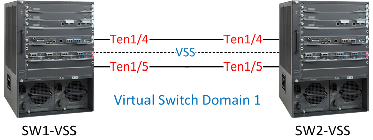
I have two 6500s, one called “SW1-VSS” and the other one is called “SW2-VSS”. I will configure them both to use virtual switch domain 1.
Let’s configure the virtual switch domain ID and switch numbers:
SW1-VSS(config)#switch virtual domain 1
Domain ID 1 config will take effect only
after the exec command 'switch convert mode virtual' is issued

SW1-VSS(config-vs-domain)#switch 1SW2-VSS(config)#switch virtual domain 1
Domain ID 1 config will take effect only
after the exec command 'switch convert mode virtual' is issued
SW2-VSS(config-vs-domain)#switch 2Both switches are configured to use virtual domain 1, SW1-VSS has been configured as “switch 1” and SW2-VSS as “switch 2”. The next step is to assign a priority to determine what switch will become active or standby.
SW1-VSS(config-vs-domain)#switch 1 priority 110
SW1-VSS(config-vs-domain)#switch 2 priority 100SW2-VSS(config-vs-domain)#switch 1 priority 110
SW2-VSS(config-vs-domain)#switch 2 priority 100The higher the priority, the more likely you will become the active switch. Switch 1 will have a priority of 110, and switch 2 a priority of 100. This means SW1-VSS will become the active switch.
Configure Virtual Switch Link
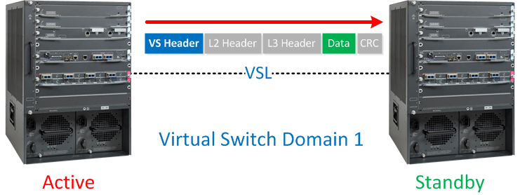
The virtual switch link is used to exchange configuration and stateful information between the two physical switches. You can use a single physical interface for VSL or create an etherchannel for redundancy. VSL will add a “virtual switch header” on each frame when it is sent on this link, basically, it looks like this:
Not all interfaces are supported for VSL. In my example, I’m using the Ten Gigabit interfaces on the Supervisors. To make sure we have redundancy, I’ll create an etherchannel using the Ten 1/4 and Ten 1/5 interfaces on the 6500s:
SW1-VSS(config)#interface port-channel 1
SW1-VSS(config-if)#no shutdown
SW1-VSS(config-if)#switch virtual link 1
SW1-VSS(config-if)#exit
SW1-VSS(config)#int range ten 1/4 - 5
SW1-VSS(config-if-range)#channel-group 1 mode on
SW1-VSS(config-if-range)#no shutSW2-VSS(config)#interface port-channel 2
SW2-VSS(config-if)#no shutdown
SW2-VSS(config-if)#switch virtual link 2
SW2-VSS(config-if)#exit
SW2-VSS(config)#int range ten 1/4 - 5
SW2-VSS(config-if-range)#channel-group 2 mode on
SW2-VSS(config-if-range)#no shutdownAs you can see above, we have a basic etherchannel configuration but I used the switch virtual link command to tell the switch that the etherchannel is a VSL interface. Let’s verify that our etherchannel is working between the two switches:
SW1-VSS#show etherchannel summary | incl Po1
1 Po1(RU) - Te1/4(P) Te1/5(P)SW2-VSS#show etherchannel summary | incl Po2
2 Po2(RU) - Te1/4(P) Te1/5(P)We are now ready to convert the 6500s to VSS.
Execute Conversion
The final step in configuring VSS is to execute the conversion. Once we do this, the switches will reload, and 3 things will happen:
- The configurations of both switches will be merged into a single configuration.
- The interface numbers will be renumbered from slot/port to switch-number/slot/port.
- Negotiation to determine which switch is active or standby.
This is how we execute the conversion:
SW1-VSS#switch convert mode virtual

This command will convert all interface names
to naming convention "interface-type switch-number/slot/port",
save the running config to startup-config and
reload the switch.

NOTE: Make sure to configure one or more dual-active detection methods
once the conversion is complete and the switches have come up in VSS mode.

Do you want to proceed? [yes/no]: yes
Converting interface names
Building configuration...SW2-VSS#switch convert mode virtual
This command will convert all interface names
to naming convention "interface-type switch-number/slot/port",
save the running config to startup-config and
reload the switch.
NOTE: Make sure to configure one or more dual-active detection methods
once the conversion is complete and the switches have come up in VSS mode.
Do you want to proceed? [yes/no]: yes
Converting interface names
Building configuration...The switches will now reboot, and you will see this on the console:
SW1-VSS#
System detected Virtual Switch configuration...
 Interface TenGigabitEthernet 1/1/4 is member of PortChannel 1
 Interface TenGigabitEthernet 1/1/5 is member of PortChannel 1
SW2-VSS#
System detected Virtual Switch configuration...
Interface TenGigabitEthernet 2/1/4 is member of PortChannel 2
Interface TenGigabitEthernet 2/1/5 is member of PortChannel 2And you will see the negotiation between active and standby:
SW1-VSS#
%PFREDUN-6-ACTIVE: Initializing as ACTIVE processor for this switch

%VSL_BRINGUP-6-MODULE_UP: VSL module in slot 1 switch 1 brought up
%VSLP-5-RRP_ROLE_RESOLVED: Role resolved as ACTIVE  by VSLP
%VSL-5-VSL_CNTRL_LINK:  New VSL Control Link  1/1/4
SW2-VSS#
%PFREDUN-6-ACTIVE: Initializing as ACTIVE processor for this switch
%VSL_BRINGUP-6-MODULE_UP: VSL module in slot 1 switch 2 brought up
%VSLP-5-RRP_ROLE_RESOLVED: Role resolved as STANDBY by VSLP
%VSL-5-VSL_CNTRL_LINK: New VSL Control Link 2/1/4The two switches rebooted, and during the boot process, the switches will detect which interfaces are used for the virtual switch link. The switches will then negotiate on the VSL to see which one becomes active or standby. As expected, SW1-VSS is the active switch.
After booting, you’ll see that the console of SW2-VSS is no longer responding. We can’t use it anymore for configuration. All configurations have to be done from the active switch now.
VSS is now up and running! Since the two switches have bonded to become one logical switch, it’s best to create a new hostname:
this is good stuff, thanks
Good work!!! When is better configure Vss instead SSO? Can work together?
VSS was created to have SSO (Stateful Switchover) + NSF (Non Stop Forwarding). When the active switch dies, the standby will take over without any downtime. SSO/NSF make sure that there is no re-convergence for (routing) protocols.
Nice, thanks
Thank you so much for great Post… its awesome…