Lesson Contents
Sometimes we see a network design where we have more than one serial link between two routers. Perhaps a single serial link doesn’t provide enough bandwidth or you want some extra redundancy. Each interface on a router requires a different IP address, so with two serial links you might end up with a design that looks like this:
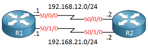
Above we see that the first link uses the 192.168.12.0/24 subnet, the second link uses 192.168.21.0/24.When we use two subnets between two routers and when you configure a routing protocol like OSPF or EIGRP, it will form two neighbor adjacencies:
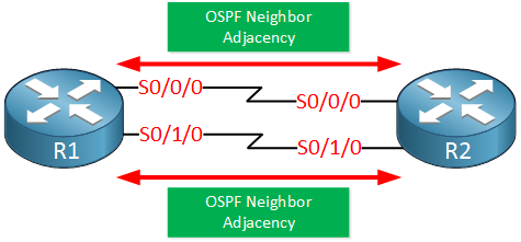
When the metric on both links is the same, our routing protocol will use load balancing so both links will be used. By default, Cisco IOS will load balance based on the destination. For example, if 2.2.2.2 would be behind R2 then R1 might use Serial 0/0/0 for all traffic destined to 2.2.2.2. Another destination might use the Serial 0/1/0 interface.
What if we add more serial links? For each serial link, we will have to configure another subnet and we will get another neighbor adjacency. It will work but we can make things much easier…
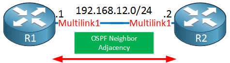
Multilink PPP allows us to combine multiple physical serial links into a single logical link. We will only need a single subnet for the logical multilink interface and if you use OSPF or EIGRP, only a single neighbor adjacency is required:
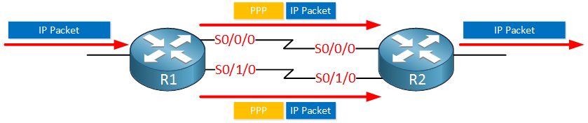
MLPPP also does load balancing on layer two. This is pretty efficient, when it receives some data like an IP packet that has to be forwarded over the multilink interface, it will fragment the IP packet in two pieces and forwards it on the multilink interface. The receiving router takes the fragments and reassembles them into the original IP packet:
By using PPP multilink, we simplify our configuration on layer three since there will be only one logical interface to work with.
Configuration
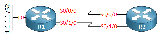
Let’s see how we configure PPP multilink. I will use the following topology:
First, don’t forget to specify a clock rate. I will check which of my routers has the DCE end of the cable:
R2#show controllers serial 0/0/0 | include clock
DCE V.35, clock rate 2000000R2#show controllers serial 0/1/0 | include clock
DCE V.35, clock rate 2000000R2 is the DCE and you can see a clock rate was configured. Let’s enable PPP encapsulation on all serial interfaces on R1:
R1(config)#interface Serial 0/0/0
R1(config-if)#encapsulation ppp

R1(config)#interface Serial 0/1/0
R1(config-if)#encapsulation ppp
And we do the same thing on R2:
R2(config)#interface Serial 0/0/0
R2(config-if)#encapsulation ppp

R2(config)#interface Serial 0/1/0
R2(config-if)#encapsulation ppp
Now we can create the multilink interface on both routers:
R1(config)#interface multilink 1
R1(config-if)#ip address 192.168.12.1 255.255.255.0
R2(config)#interface multilink 1
R2(config-if)#ip address 192.168.12.2 255.255.255.0
You can pick whatever multilink interface number you like, just make sure that it’s the same on both ends. This is where we configure the IP address.
On the physical serial interfaces, we have to configure to which multilink interface they belong with the ppp multilink group command. Let’s start with R1:
R1(config)#interface Serial 0/0/0
R1(config-if)#ppp multilink group 1

R1(config)#interface Serial 0/1/0
R1(config-if)#ppp multilink group 1
And let’s do the same thing on R2:
R2(config)#interface Serial 0/0/0
R2(config-if)#ppp multilink group 1

R2(config)#interface Serial 0/1/0
R2(config-if)#ppp multilink group 1
That takes care of the PPP multilink configuration.
To see the PPP multilink interface in action, let’s configure OSPF on both routers:
R1(config)#router ospf 1
R1(config-router)#network 192.168.12.0 0.0.0.255 area 0
R1(config-router)#network 1.1.1.1 0.0.0.0 area 0R2(config)#router ospf 1
R2(config-router)#network 192.168.12.0 0.0.0.255 area 0That completes our configuration.
Verification
Let’s verify our work step-by-step. First, let me quickly show you multilink interface in the running configuration:
R1#show run interface Multilink1
Building configuration...

Current configuration : 105 bytes
!
interface Multilink1
 ip address 192.168.12.1 255.255.255.0
 ppp multilink
 ppp multilink group 1
end
We only created the multilink 1 interface and configured an IP address but you can see that Cisco IOS automatically added the ppp multilink and ppp multilink group commands.
Let’s continue, I want to make sure that the physical interfaces are up and running:
R1#show interfaces Serial 0/0/0 | include line protocol
Serial0/0/0 is up, line protocol is upR1#show interfaces Serial 0/1/0 | include line protocol
Serial0/1/0 is up, line protocol is up The interfaces are up/up which tells us that the clock rate is configured correctly and that PPP encapsulation is configured on both ends. Let’s take a look at the multilink interface:
R1#show interfaces multilink 1
Multilink1 is up, line protocol is up
  Hardware is multilink group interface
  Internet address is 192.168.12.1/24
  MTU 1500 bytes, BW 3088 Kbit/sec, DLY 20000 usec,
     reliability 255/255, txload 1/255, rxload 1/255
  Encapsulation PPP, LCP Open, multilink Open
The multilink interface is up too, it also shows me the IP address. Let’s take a closer look at the PPP details of the multilink interface:
R1#show ppp multilink

Multilink1
  Bundle name: R2
  Remote Endpoint Discriminator: [1] R2
  Local Endpoint Discriminator: [1] R1
  Bundle up for 00:06:00, total bandwidth 3088, load 1/255
  Receive buffer limit 24000 bytes, frag timeout 1000 ms
    0/0 fragments/bytes in reassembly list
    0 lost fragments, 3 reordered
    0/0 discarded fragments/bytes, 0 lost received
    0x26 received sequence, 0x2A sent sequence
  Member links: 2 active, 0 inactive (max 255, min not set)
    Se0/0/0, since 00:06:00
    Se0/1/0, since 00:05:53
No inactive multilink interfaces
The output above tells me that the multilink interface is up and has bundled Serial 0/0/0 and Serial 0/1/0 to the multilink interface. One more command to verify the PPP multilink interface, let’s look at its IP settings:

Hello Vianney
Take a look at this lesson on PPP Multilink. It describes the configuration and various principles that you need to keep in mind. Take a look, and if you have any questions or concerns, let us know.
https://networklessons.com/cisco/ccna-routing-switching-icnd2-200-105/ppp-multilink
I hope this has been helpful!
Laz
Hi Vianney,
From what I know, PPP multilink is reliable and shouldn’t impact your latency/bandwidth. It’s also used in VoIP scenarios where they recommend to enable interleaving. When you do this, the smaller (delay sensitive) packets are not multilink encapsulated.
If you want a definitive answer, it would be best just to test this. Lab it up on some real hardware, then see how it compares against two regular PPP links.
Rene