Shaping is a QoS (Quality of Service) technique that we can use to enforce lower bitrates than what the physical interface is capable of. Most ISPs use shaping or policing to enforce “traffic contracts” with their customers. When we use shaping we will buffer the traffic to a certain bitrate, policing will drop the traffic when it exceeds a certain bitrate. Let’s discuss an example of why you want to use shaping:
Your ISP sold you a fiber connection with a traffic contract and a guaranteed bandwidth of 10 Mbit, the fiber interface however is capable of sending 100 Mbit per second. Most ISPs will configure policing to drop all traffic above 10 Mbit so that you can’t get more bandwidth than what you are paying for. It’s also possible that they shape it down to 10 Mbit, but shaping means they have to buffer data, while policing means they can just throw it away. The 10 Mbit that we pay for is called the CIR (Committed Information Rate).
There are two reasons why you might want to configure shaping:
- Instead of waiting for the policer of the ISP to drop your traffic, you might want to shape your outgoing traffic towards the ISP so that they don’t drop it.
- To prevent egress blocking. When you go from a high-speed interface to a low-speed interface you might get packet loss (tail drop) in your outgoing queue. We can use shaping to ensure everything will be sent (until its buffer is full).
In short, we configure shaping when we want to use a “lower bitrate” than what the physical interface is capable of.
Routers are only able to send bits at the physical clock rate. As network engineers, we think we can do pretty much anything, but it’s impossible to make an electrical or optical signal crawl slower through the cable just because we want to. If we want to get a lower bitrate, we will have to send some packets, pause for a moment, send some packets, pause for a moment…and so on.
For example, let’s say we have a serial link with a bandwidth of 128 kbps. Imagine we want to shape it to 64 kbps. If we want to achieve this we need to make sure that 50% of the time we are sending packets and 50% of the time we are pausing. 50% of 128 kbps = an effective CIR of 64 kbps.
For another example, let’s say we have the same 128 kbps link, but the CIR rate is 96 kbps. This means we will send 75% of the time and pause 25% of the time (96 / 128 = 0.75).
Now you have a basic idea of what shaping is, let’s take a look at a shaping example so I can explain some terminology:
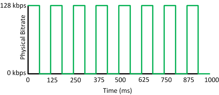
Above, we see an interface with a physical bitrate of 128 kbps that has been configured to shape to 64 kbps. On the vertical line, you can see the physical bitrate of 128 kbps. Horizontally you can see the time from 0 to 1000 milliseconds. The green line indicates when we send traffic and pause traffic. For the first 62.5 ms we are sending traffic at 128 kbps and for the second 62.5 ms we are pausing. This first interval takes 125 ms (62.5 + 62.5 = 125 ms) and we call this interval the Tc (Time Interval).
In total, there are 8 time intervals of 125 ms each. 8x 125 ms = 1000 ms. Most Cisco routers have a Tc default value of 125 ms. With the example above, we are sending traffic 50% of the time and pausing 50% of the time. 50% of 128 kbps = shaping rate of 64 kbps.
Our Cisco router will calculate how many bits it can send each Tc so that it will reach the targetted shaping rate. This value is called the Bc (committed burst).
In the example above, the Bc is 8.000 bits. Each Tc (125 ms) it will send 8.000 bits, and when it’s done it will wait until the Tc expires. In total, we have 1.000 ms of time. When we divide 1.000 ms by 125 ms, we have 8 Tcs. 8000 bits x 8 Tcs = shaping rate of 64 kbps.
To sum things up, this is what you have learned so far:
- Tc (time interval) is the time in milliseconds over which we can send the Bc (committed burst).
- Bc (committed burst) is the amount of traffic we can send during the Tc (time interval) and is measured in bits.
- CIR (committed information rate) is the bitrate that is defined in the “traffic contract” that we received from the ISP.
There are several formulas that we can use to calculate the values above:
Bc value:
Bc = Tc * CIRIn the example above, we have a Tc of 125 ms, and we are shaping to 64 kbps (that’s the CIR), so the formula will be:
125 ms * 64 kbps = 8.000 bits.
Tc value:
Tc = Bc / CIRWe just calculated the Bc (8.000 bits), and the CIR rate is 64 kbps. The formula will be:
8.000 bits / 64.000 = 0.125. So that’s 125 ms.
Let’s look at another example. Imagine we have an interface with a physical bitrate of 256 kbps, and we are shaping to 128 kbps. How many bits will we send each Tc?
CIR = 128 kbps
TC = 125 ms (the default)
125 ms x 128 kbps = 16.000 bits
So the Bc is 16.000 bits. For each Tc, we will send 16.000 bits.
The shaper will grab 16.000 bits each Tc and send them. Once they are sent, it will wait until the Tc has expired, and a new Tc will start.
The cool thing about shaping is that all traffic will be sent since we are buffering it. The downside of buffering traffic is that it introduces delay and jitter. Let me show you an example:
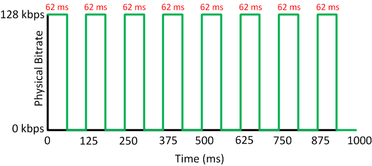
Above we have the same interface with a physical bitrate of 128 kbps and the Tc is 125 ms. Shaping has been configured for 64 kbps. You can see that each Tc it takes 62 ms to send the Bc. How did I come up with this number? Let me walk you through it:
125 ms * 64 kbps = 8.000 bits.
Now we know the Bc, we can calculate how long it takes for a 128 kbps interface to send these 8000 bits. This is how you do it:
Delay value:
Delay = Bc / physical bitrateLet’s try this formula to find out how long it takes for our 128kbps interface to send 8.000 bits:
8.000 / 128.000 = 0.0625
So it takes 62.5 ms to send 8000 bits through a 128 kbps interface. If we have a fast interface, the delay will, of course be a lot lower. Let’s say we have a T1 interface (1.54 Mbit):
8.000 / 1.540.000 = 0.0051
It only takes 5 ms to send 8000 bits through a T1 interface.
The default Tc of 125 ms is maybe not a very good idea when you are working with Voice over IP. Imagine that we are sending a data packet that is exactly 8.000 bits over this T1 link. It will only take 5 ms, but that means that we are waiting 120 ms ( 125 ms – 5 ms) before the Tc expires, and we can send the next 8.000 bits. If this next packet is a VoIP packet, then it will at least be delayed by 120 ms.
Cisco recommends a one-way delay of 150 to 200 ms for real-time traffic like VoIP, so wasting 120 ms just waiting isn’t a very good idea. When you have real-time traffic like voice, Cisco recommends setting your Tc to 10ms to keep the delay to a minimum.
So if we set our Tc to 10 ms instead of the default 125 ms…what will our Bc be? In other words, how many bits can we send during the Tc of 10 ms?
Let’s get back to our 128 kbps interface that is configured to shape to 64 kbps to calculate this:
Excellent post, good explanation. Both terms, shaping and policing are complex to understand.
Hi Rene, Great explanation of shaping, its quite hard to find this sort of detail in an easy to understand format. One question regarding rate-limiting vs shaping. Although rate-limiting does not buffer/queue packets, is it capable of slowing the rate to the contracted bandwidth? For example, if I have a 1GB fibre to a provider switch but only have say 50mb contracted, can I use rate-limiting to prevent the router transmitting at a 1GB clock rate or is shaping the only method of achieving this?
Hi Brendan, glad to hear you like it. Do you refer to rate-limiting on a router or switch?
On routers you have the “rate-limit” command but it’s the “legacy QoS” method of configuring policing, it can be applied inbound or outbound.
On the Catalyst Switches (eg 3560) you can use the "srr-queue bandwidth limit " to limit outgoing traffic but I believe this is a shaper.
This is one awesome posts about QoS policing and shaping .U don’t find like this many out there.And I should thank U for this.
BTW, I have few questions reg this,
1.In this example that you have demonstrated on what basis the Tc (Time Interval) value was chosen. i,e 62.5 in this case ? (62.5 + 62.5 =125).Is there any logic behind it?
Expecting the earliest reply..
Thanks in Advance,
SVP
Hi Sai,
I’m glad to hear that you like it. Cisco routers have a default Tc of 125 ms so that there are 8 intervals, not sure why they decided to go with this value. You can change it if you like it to a lower value (10 ms on most Cisco routers) which is a good idea for VoIP traffic…
Rene