Lesson Contents
IGMP Proxy allows hosts in a UDLR (Unidirectional Link Routing) topology that are not directly connected to a downstream router to join a multicast group from an upstream router by using a back channel.
To understand IGMP proxy, let’s first look at what a UDL (Unidirectional Link) is. A UDL is a link where traffic only goes one way. Where do we see this? Here’s an example:
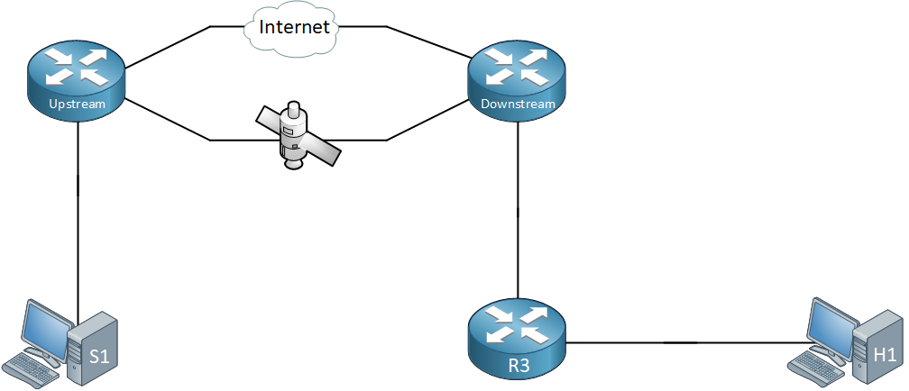
Above we have three multicast routers. There’s a router called upstream, downstream, and R3. The upstream and downstream routers are connected with two links:
- One unidirectional satellite link.
- One regular Internet connection.
Some satellite links are unidirectional which means that we can only send traffic from the upstream router to the downstream router, not the other way around. This causes issues with routing protocols like OSPF or EIGRP but also with multicast traffic. Receiving multicast traffic through the satellite link is no problem but our downstream router is unable to let the upstream router know that it wants to receive or prune multicast traffic.
To solve this, we can use a back channel. The back channel is a regular interface, like an Internet connection. The downstream router can use the back channel to inform the upstream router that it wants to receive certain multicast traffic. It does this by “proxying” an IGMP membership report.
When the upstream router receives the IGMP membership report, it will create a forwarding entry for the UDL interface. Here’s an image that helps you visualize this:
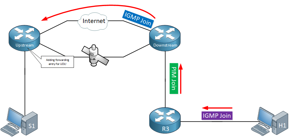
Here’s what you see above:
- H1 (our receiver) wants to join a multicast group so it sends an IGMP join (membership report) to R3.
- R3 processes the IGMP membership report and sends a PIM join to its RP (the downstream router).
- The downstream router receives the PIM join and creates a (*,G) forwarding entry in its multicast routing table.
- The downstream router proxies an IGMP membership report over the back channel to the upstream router.
- The upstream router receives the IGMP membership report and creates a forwarding entry for the UDL link.
- Multicast traffic is now forwarded over the UDL link from the upstream router to the downstream router.
Configuration
Let’s take a look at this in action. I’ll use the topology above but added some interface numbers:
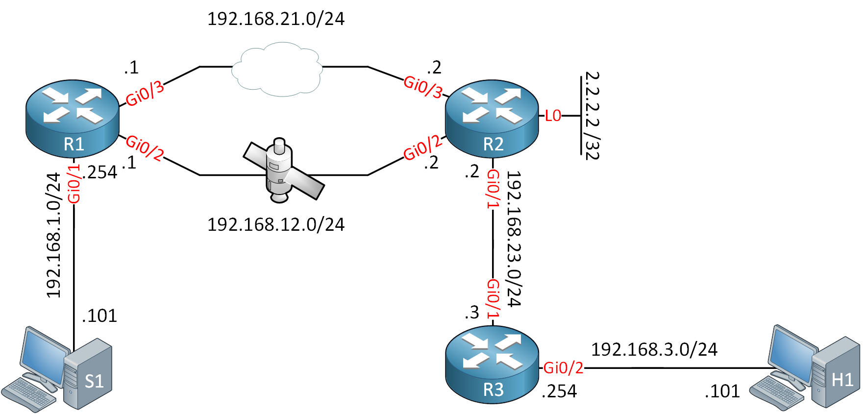
R1 is our upstream router, R2 our downstream router. R1 uses PIM dense mode while R2 / R3 use PIM sparse mode. R2 has a loopback interface with IP address 2.2.2.2 that is used as the RP.
The GigabitEthernet 0/2 interface on R1 and R2 is our “unidirectional satellite link”. The GigabitEthernet 0/3 interface is an Internet connection. I’ll use an inbound access-list on R1 which blocks all inbound traffic to simulate the satellite link.
First, we need to enable multicast routing on all routers:
R1, R2 & R3
(config)#ip multicast-routing
R1 – Upstream Router
Let’s configure our upstream router. We need to enable PIM dense mode on all interfaces:
R1(config)#interface GigabitEthernet 0/1
R1(config-if)#ip pim dense-mode

R1(config)interface GigabitEthernet 0/2
R1(config-if)#ip pim dense-mode
Let’s create the access-list on R1 so that all inbound traffic is denied:
R1(config)#ip access-list standard DENY_EVERYTHING
R1(config-std-nacl)#deny any

R1(config)#interface GigabitEthernet 0/2
R1(config-if)#ip access-group DENY_EVERYTHING in
We also need to enable PIM and configure the interface as unidirectional:
R1(config)#interface GigabitEthernet 0/2
R1(config-if)#ip pim dense-mode
R1(config-if)#ip igmp unidirectional-link
Last but not least, I’ll create a default route so that all traffic is forwarded through the unidirectional link:
R1(config)#ip route 0.0.0.0 0.0.0.0 192.168.12.2That completes our configuration on the upstream router.
R2 – Downstream Router
Let’s work on the downstream router. I’ll enable PIM and we tell the router that this is the UDL link:
R2(config)#interface GigabitEthernet 0/2
R2(config-if)#ip pim sparse-mode
R2(config-if)#ip igmp unidirectional-link
On the interface that connects to R3, we enable PIM and add the ip igmp mroute-proxy command:
R2(config)#interface GigabitEthernet 0/1
R2(config-if)#ip pim sparse-mode
R2(config-if)#ip igmp mroute-proxy loopback 0
This command enables forwarding of IGMP membership reports to a “proxy interface” (loopback 0) for all (*,G) forwarding entries that we have on our GigabitEthernet 0/1 interface.
Let’s configure that loopback interface:
R2(config)#interface Loopback 0
R2(config-if)#ip pim sparse-mode
R2(config-if)#ip igmp proxy-service
R2(config-if)#ip igmp helper-address udl GigabitEthernet 0/2
Besides adding PIM, we use two important commands:
- ip pim proxy-service: this command enables the actual proxying of IGMP membership reports.
- ip igmp helper-address udl: this command tells the router to send IGMP membership reports to an upstream router that is connected on our UDL interface.
R2 is the RP in our network. Let’s configure it statically:
R2(config)#ip pim rp-address 2.2.2.2We also have to configure some routing. R2 needs to know how to reach the 192.168.1.0/24 for two reasons:
- I’d like my receiver to be able to reply to the ICMP requests that I’ll send from my source.
- R2 will forward IGMP membership reports to the IGMP querier, and as you’ll see in a bit, the IP address of the IGMP querier will be 192.168.1.254.
I’ll use a static route:
R2(config)#ip route 192.168.1.0 255.255.255.0 192.168.21.1Between R2 and R3, let’s use OSPF so that R3 can reach the RP address (2.2.2.2) and the subnet of our source:
R2(config)#router ospf 1
R2(config-router)#network 2.2.2.2 0.0.0.0 area 0
R2(config-router)#network 192.168.23.0 0.0.0.255 area 0
R2(config-router)#redistribute static subnets metric 1
R3
We don’t require anything special on R3. Let’s enable PIM sparse mode on its interfaces:
R3(config)#interface GigabitEthernet 0/1
R3(config-if)#ip pim sparse-mode

R3(config)#interface GigabitEthernet 0/2
R3(config-if)#ip pim sparse-mode
And configure 2.2.2.2 as the RP address:
R3(config)#ip pim rp-address 2.2.2.2OSPF is used so that we can get to the RP address and the remote subnet of the source:
R3(config)#router ospf 1
R3(config-router)#network 192.168.3.0 0.0.0.255 area 0
R3(config-router)#network 192.168.23.0 0.0.0.255 area 0
Verification
Let’s verify our work. Let’s take a look at our UDL interface on R1 and R2:
R1#show ip igmp interface GigabitEthernet 0/2
GigabitEthernet0/2 is up, line protocol is up
  Internet address is 192.168.12.1/24
  IGMP is enabled on interface
  Current IGMP host version is 2
  Current IGMP router version is 2
  IGMP query interval is 60 seconds
  IGMP configured query interval is 60 seconds
  IGMP querier timeout is 120 seconds
  IGMP configured querier timeout is 120 seconds
  IGMP max query response time is 10 seconds
  Last member query count is 2
  Last member query response interval is 1000 ms
  Inbound IGMP access group is not set
  IGMP activity: 1 joins, 0 leaves
  Multicast routing is enabled on interface
  Multicast TTL threshold is 0
  Multicast designated router (DR) is 192.168.12.1 (this system)
  IGMP querying router is 192.168.1.254 (this system)
  IGMP unidirectional link multicast routing enabled
No multicast groups joined by this systemR2#show ip igmp interface GigabitEthernet 0/2
GigabitEthernet0/2 is up, line protocol is up
Internet address is 192.168.12.2/24
IGMP is enabled on interface
Current IGMP host version is 2
Current IGMP router version is 2
IGMP query interval is 60 seconds
IGMP configured query interval is 60 seconds
IGMP querier timeout is 120 seconds
IGMP configured querier timeout is 120 seconds
IGMP max query response time is 10 seconds
Last member query count is 2
Last member query response interval is 1000 ms
Inbound IGMP access group is not set
IGMP activity: 0 joins, 0 leaves
Multicast routing is enabled on interface
Multicast TTL threshold is 0
Multicast designated router (DR) is 192.168.12.2 (this system)
IGMP querying router is 192.168.1.254
IGMP unidirectional link multicast routing enabled
No multicast groups joined by this systemAbove, we see that the GigabitEthernet 0/2 interface is a UDL link and that we use unidirectional link multicast routing. It also tells us that the IGMP querier address is 192.168.1.254 (R1).
To see the proxying in action, I’ll enable IGMP debugging on R1 and R2:
R1 & R2
#debug ip igmp
IGMP debugging is on
Now let’s join a multicast group on our receiver:
H1(config)#interface GigabitEthernet 0/1
H1(config-if)#ip igmp join-group 239.1.1.1
Here’s what we get on R2:
R2#
IGMP(0): Sending Unsolicited Proxy Report to Loopback0 for 239.1.1.1 on GigabitEthernet0/1
IGMP(0): Sending Proxy Report for 239.1.1.1 to Loopback0
IGMP(0): Received v2 Report on Loopback0 from 2.2.2.2 for 239.1.1.1
IGMP(0): Received Group record for group 239.1.1.1, mode 2 from 2.2.2.2 for 0 sources
IGMP(0): WAVL Insert group: 239.1.1.1 interface: Loopback0Successful
IGMP(0): Switching to EXCLUDE mode for 239.1.1.1 on Loopback0
IGMP(0): Updating EXCLUDE group timer for 239.1.1.1
IGMP(0): MRT Add/Update Loopback0 for (*,239.1.1.1) by 0
IGMP(0): Helper Report for group 239.1.1.1 to 192.168.1.254 for UDL GigabitEthernet0/2
IGMP(0): Received v2 Report on GigabitEthernet0/2 from 192.168.12.2 for 239.1.1.1
The debug on R2 is nice and clean. It shows us that it forwards the proxy report to our loopback interface and then sends a “helper report” for its UDL interface.
This proxied membership report is sent with unicast:
Frame 1: 46 bytes on wire (368 bits), 46 bytes captured (368 bits) on interface 0
Ethernet II, Src: fa:16:3e:87:13:29 (fa:16:3e:87:13:29), Dst: fa:16:3e:bd:13:5b (fa:16:3e:bd:13:5b)
Internet Protocol Version 4, Src: 192.168.12.2, Dst: 192.168.1.254
    0100 .... = Version: 4
    .... 0110 = Header Length: 24 bytes (6)
    Differentiated Services Field: 0xc0 (DSCP: CS6, ECN: Not-ECT)
    Total Length: 32
    Identification: 0x00c2 (194)
    Flags: 0x00
    Fragment offset: 0
    Time to live: 255
    Protocol: IGMP (2)
    Header checksum: 0x9604 [validation disabled]
    [Header checksum status: Unverified]
    Source: 192.168.12.2
    Destination: 192.168.1.254
    [Source GeoIP: Unknown]
    [Destination GeoIP: Unknown]
    Options: (4 bytes), Router Alert
Internet Group Management Protocol
    [IGMP Version: 2]
    Type: Membership Report (0x16)
    Max Resp Time: 0.0 sec (0x00)
    Checksum: 0xf9fc [correct]
    [Checksum Status: Good]
    Multicast Address: 239.1.1.1
Packet Capture: Multicast IGMP Proxy Membership Report
Let’s take a look at R1:
R1#
IGMP(0): Received v2 Report on GigabitEthernet0/2 from 192.168.12.2 for 239.1.1.1
IGMP(0): Received Group record for group 239.1.1.1, mode 2 from 192.168.12.2 for 0 sources
IGMP(0): WAVL Insert group: 239.1.1.1 interface: GigabitEthernet0/2Successful
IGMP(0): Switching to EXCLUDE mode for 239.1.1.1 on GigabitEthernet0/2
IGMP(0): Updating EXCLUDE group timer for 239.1.1.1
IGMP(0): MRT Add/Update GigabitEthernet0/2 for (*,239.1.1.1) by 0
IGMP(0): Forward Report for group 239.1.1.1 down UDL GigabitEthernet0/2
R1 has received the IGMP membership report from R2 and you can see that it adds an entry for (*,239.1.1.1) on its GigabitEthernet 0/2 interface. It also forwards the report down the UDL link, it does this so that all downstream routers (in case you have more than one) see the membership report, which suppresses unnecessary membership reports that are generated by downstream routers.
You can use the show ip igmp groups command to see if R1 received the membership report:
R1#show ip igmp groups
IGMP Connected Group Membership
Group Address    Interface                Uptime    Expires   Last Reporter   Group Accounted
239.1.1.1        GigabitEthernet0/2       00:04:15  00:02:36  192.168.12.2
224.0.1.40       GigabitEthernet0/1       00:06:26  00:02:36  192.168.1.254
R1 shows an entry for the 239.1.1.1 multicast group with its UDL link. R2 is our reporter. You can also use the show ip igmp udlr command:
R1#show ip igmp udlr
IGMP UDLR Status, UDL Interfaces: GigabitEthernet0/2
Group Address    Interface                UDL Reporter     Reporter Expires
239.1.1.1        GigabitEthernet0/2       192.168.12.2     00:02:34
The output of this command is similar. It shows up our UDL interface, the multicast group, and the reporter. You can see similar information from R2:
R2#show ip igmp groups
IGMP Connected Group Membership
Group Address    Interface                Uptime    Expires   Last Reporter   Group Accounted
239.1.1.1        Loopback0                00:03:32  00:02:18  2.2.2.2
224.0.1.40 Loopback0 00:05:41 00:02:21 2.2.2.2R2#show ip igmp udlr
IGMP UDLR Status, UDL Interfaces: GigabitEthernet0/2
Group Address Interface UDL Reporter Reporter Expires
239.1.1.1 Loopback0 192.168.12.2 00:02:13
224.0.1.40 Loopback0 0.0.0.0 stoppedLet’s generate some traffic, and see what we get:
S1#ping 239.1.1.1 repeat 5
Type escape sequence to abort.
Sending 5, 100-byte ICMP Echos to 239.1.1.1, timeout is 2 seconds:
.
Reply to request 1 from 192.168.3.101, 56 ms
Reply to request 2 from 192.168.3.101, 12 ms
Reply to request 3 from 192.168.3.101, 11 ms
Reply to request 4 from 192.168.3.101, 10 ms
Our pings are working. Let’s check the multicast routing tables:
R1#show ip mroute 239.1.1.1

(*, 239.1.1.1), 00:05:20/stopped, RP 0.0.0.0, flags: DC
  Incoming interface: Null, RPF nbr 0.0.0.0
  Outgoing interface list:
    GigabitEthernet0/2, Forward/Dense, 00:05:20/stopped

(192.168.1.101, 239.1.1.1), 00:02:31/00:00:28, flags: T
  Incoming interface: GigabitEthernet0/1, RPF nbr 0.0.0.0
  Outgoing interface list:
    GigabitEthernet0/2, Forward/Dense, 00:02:31/stopped
R1 is forwarding multicast traffic down its GigabitEthernet 0/2 link. Let’s check R2:
R2#show ip mroute 239.1.1.1

(*, 239.1.1.1), 00:05:40/00:02:45, RP 2.2.2.2, flags: SJC
  Incoming interface: Null, RPF nbr 0.0.0.0
  Outgoing interface list:
    GigabitEthernet0/1, Forward/Sparse, 00:05:40/00:02:45
    GigabitEthernet0/2, Forward/Dense, 00:05:40/stopped

(192.168.1.101, 239.1.1.1), 00:02:50/00:00:09, flags: T
  Incoming interface: GigabitEthernet0/2, RPF nbr 0.0.0.0
  Outgoing interface list:
    GigabitEthernet0/1, Forward/Sparse, 00:02:50/00:02:45
R2 is receiving the traffic on its GigabitEthernet 0/2 link. This is looking good!
Hi René,
Under the loopback. what exact command? Is i pim proxy-server or service?
BR,
Ulrich
Hi Rene,
In the picture, R2 has two interfaces Gi0/2, and I think interface towards R3 should be Gi0/1
FYI
Regards
Thanks Adrian, it has been fixed.
Hi Ulrich,
Here’s the loopback of R2:
You can find the complete configurations of all routers at the end of the lesson
Rene
R2(config-if)#ip igmp helper-address udl GigabitEthernet 0/2ip igmp helper-address udl: this command tells the router to send IGMP membership reports to an upstream router that is connected on our UDL interface.
Why are we forwarding traffic to R2 Gig 0/2 towards R1 Gig 0/2 when R1 is blocking all income traffic?
R2(config-if)#ip igmp unidirectional-linkIf it is unidirectional how would we know if traffic is inbound or outbound only?
Thanks