The PIM prune mechanism works a bit different on multi-access links compared to point-to-point links.
On point to point links there is only one other router on the other end so when we receive a prune message, it’s safe to stop forwarding the traffic. On multi-access links however it’s possible that we have more than one downstream router that is interested in receiving the multicast traffic. When we receive a prune on a multi-access link, we need to make sure that nobody else still wants to receive it. This is done with the prune override mechanism and it applies to both PIM dense and sparse mode.
Here’s an example:
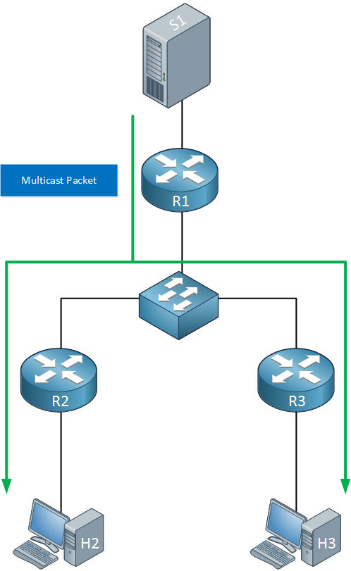
Above we have a source (S1) sending multicast traffic to R1. At the bottom are two receivers (H2 and H3) so R2/R3 are both forwarding the traffic. After a few minutes, H2 doesn’t want to receive this traffic anymore:
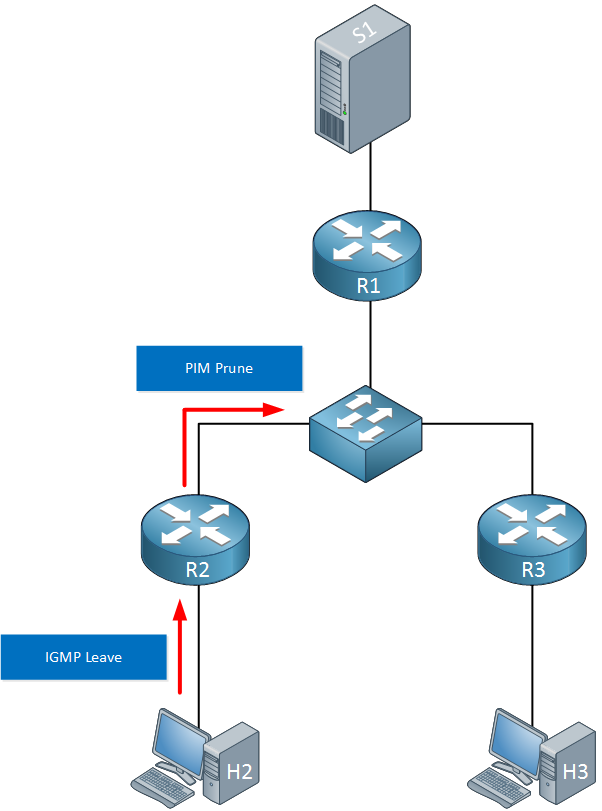
H2 will send an IGMP leave towards R2 who will send a PIM prune to its upstream neighbor, R1. This PIM prune message is destined to 224.0.0.13 so R1 and R3 will both receive it. Here’s what happens next:
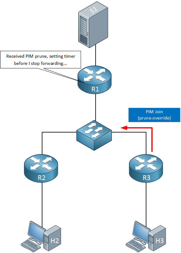
R1 receives the prune message but it won’t stop forwarding right away. It will wait for a few seconds to see if other routers are still interested. R3 is still interested so it will send a PIM join. Since this PIM join overrides the prune, we call it a prune override but the packet is a regular PIM join.. R1 now knows what to do:
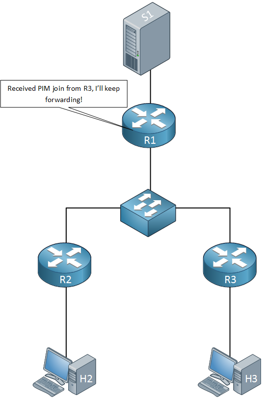
Since R3 is still interested, R1 will ignore the prune message from R2 and will keep forwarding the multicast traffic.
Let’s take a look at some real routers to see how this works in action!
Configuration
Here’s the topology I will use:
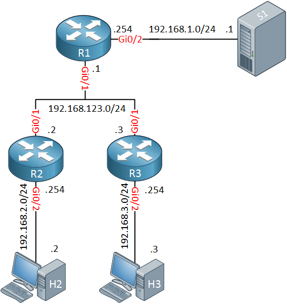
Above we have a small network with three routers. S1 will send multicast packets and H2/H3 will be the receivers. OSPF has been configured as the unicast routing protocol and PIM dense mode for multicast routing. If you want to test this example yourself, you can find the startup configurations below:
Startup Configurations
Want to take a look for yourself? Here you will find the final configuration of each device.
R1
hostname R1
!
ip multicast-routing
ip cef
!
interface GigabitEthernet0/1
 ip address 192.168.123.1 255.255.255.0
 ip pim dense-mode
 duplex auto
 speed auto
 media-type rj45
!
interface GigabitEthernet0/2
 ip address 192.168.1.254 255.255.255.0
 ip pim dense-mode
 duplex auto
 speed auto
 media-type rj45
!
router ospf 1
 network 192.168.1.0 0.0.0.255 area 0
 network 192.168.123.0 0.0.0.255 area 0
!
end
R2
hostname R2
!
ip multicast-routing
ip cef
!
interface GigabitEthernet0/1
 ip address 192.168.123.2 255.255.255.0
 ip pim dense-mode
 duplex auto
 speed auto
 media-type rj45
!
interface GigabitEthernet0/2
 ip address 192.168.2.254 255.255.255.0
 ip pim dense-mode
 duplex auto
 speed auto
 media-type rj45
!
router ospf 1
 network 192.168.2.0 0.0.0.255 area 0
 network 192.168.123.0 0.0.0.255 area 0
!
end
R3
hostname R3
!
ip multicast-routing
ip cef
!
interface GigabitEthernet0/1
 ip address 192.168.123.3 255.255.255.0
 ip pim dense-mode
 duplex auto
 speed auto
 media-type rj45
!
interface GigabitEthernet0/2
 ip address 192.168.3.254 255.255.255.0
 ip pim dense-mode
 duplex auto
 speed auto
 media-type rj45
!
router ospf 1
 network 192.168.3.0 0.0.0.255 area 0
 network 192.168.123.0 0.0.0.255 area 0
!
end
H2
hostname H2
!
no ip routing
!
interface GigabitEthernet0/1
 ip address 192.168.2.2 255.255.255.0
 no ip route-cache
 duplex auto
 speed auto
 media-type rj45
!
ip default-gateway 192.168.2.254
!
end
H3
hostname H3
!
no ip routing
!
interface GigabitEthernet0/1
 ip address 192.168.3.3 255.255.255.0
 no ip route-cache
 duplex auto
 speed auto
 media-type rj45
!
ip default-gateway 192.168.3.254
!
end
S1
hostname S1
!
no ip routing
!
interface GigabitEthernet0/1
 ip address 192.168.1.1 255.255.255.0
 no ip route-cache
 duplex auto
 speed auto
 media-type rj45
!
ip default-gateway 192.168.1.254
!
end
Let’s configure the hosts to receive our multicast traffic:
H2 & H3
(config)#interface GigabitEthernet 0/1
(config-if)#ip igmp join-group 239.1.1.1
And generate some traffic from S1:
S1#ping 239.1.1.1 repeat 1000
Type escape sequence to abort.
Sending 1000, 100-byte ICMP Echos to 239.1.1.1, timeout is 2 seconds:
.
Reply to request 1 from 192.168.2.2, 20 ms
Reply to request 2 from 192.168.3.3, 5 ms
S1 is receiving replies from H2 and H3. Let’s check the multicast routing tables of R2 and R3:
R2#show ip mroute 239.1.1.1 192.168.1.1

(192.168.1.1, 239.1.1.1), 01:51:50/00:01:33, flags: T
  Incoming interface: GigabitEthernet0/1, RPF nbr 192.168.123.1
  Outgoing interface list:
GigabitEthernet0/2, Forward/Dense, 00:00:36/stoppedR3#show ip mroute 239.1.1.1 192.168.1.1
(192.168.1.1, 239.1.1.1), 01:52:29/00:01:55, flags: T
Incoming interface: GigabitEthernet0/1, RPF nbr 192.168.123.1
Outgoing interface list:
GigabitEthernet0/2, Forward/Dense, 01:52:29/stoppedBoth router are forwarding traffic to the hosts. Before we configure H2 to stop listening, let’s enable a debug:
R1, R2 & R3
#debug ip pim
PIM debugging is on
Let’s configure H2 to stop listening:
H2(config)#interface GigabitEthernet 0/1
H2(config-if)#no ip igmp join-group 239.1.1.1
Here’s what we we will see on R2:
R2#
PIM(0): Insert (192.168.1.1,239.1.1.1) prune in nbr 192.168.123.1's queue
PIM(0): Building Join/Prune packet for nbr 192.168.123.1
PIM(0):  Adding v2 (192.168.1.1/32, 239.1.1.1) Prune
PIM(0): Send v2 join/prune to 192.168.123.1 (GigabitEthernet0/1)
PIM(0): Received v2 Join/Prune on GigabitEthernet0/1 from 192.168.123.1, not to us
PIM(0): Prune-list: (192.168.1.1/32, 239.1.1.1)
PIM(0): Received v2 Join/Prune on GigabitEthernet0/1 from 192.168.123.3, not to us
PIM(0): Join-list: (192.168.1.1/32, 239.1.1.1)
R2 sends the prune message to its upstream neighbor, R1. Here’s what R1 thinks of it:


Hi Rene,
Very nice article. I was curious about the value of the timer on R1 once it receives prune message from the R2
Thanks
Nage
So R2 will keep receiving the multicast stream even though it does not have a receiver. I wonder if the switch(es) sitting in the middle of the Multiaccess segment can do something to avoid sending the multicast stream to R2 once it sends the PIM Prune msg.
Hello Muhmmad
That’s a good question. It would seem that something like IGMP snooping could be used in such a case to ensure unwanted multicast traffic doesn’t reach a router like that. Although Layer 2 switches are IGMP-aware and can deal with delivering multicast traffic only to hosts that want it, they are unable to act upon PIM messages such as PIM prune in the same way, to help in making such communication more efficient.
In such a case, a network designer should choose a better topology, such as ensuring that R2 and R3 are in different network segments.
... Continue reading in our forumHi,
Could you explain why R1 will “relay” the prune message by sending it again with itself as the source?When R2&R3 receive it, will they relay it again?If so this seems to cause a problem.If not,why?
Thanks
Hello Kai
This is a tricky one. The simple answer is that the Multicast Dense Mode process requires that the upstream router that receives a prune message on its interface that exists on a multi-access (shared) medium such as Ethernet must respond with a prune message.
The process that upstream multicast routers must follow is called the Upstream(S,G) State Machine. This is a fancy term for the steps and processes that define what such a router will do when certain events take place.
This state machine is described in its entirety in RFC 3973. In particular,
... Continue reading in our forum