Lesson Contents
EIGRP is normally pretty straight-forward to configure. You type in the correct network commands, routers become neighbors and start exchanging routing information.
Frame-relay is an exception though…it’s no problem to run EIGRP on a frame-relay network but there are some small issues we might have to deal with. We can configure our frame-relay network as multipoint or point-to-point, the multipoint setup will introduce issues when you use a hub and spoke topology.
Let’s take a look at both scenarios. You will learn about the issues and how to deal with them. Here’s the topology I will use:
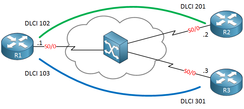
Above we have three routers, R1 is our hub and R2/R3 are spoke routers. You can see the DLCI numbers in the picture above or you can find them on your routers:
R1#show frame-relay pvc | include DLCI
DLCI = 102, DLCI USAGE = LOCAL, PVC STATUS = ACTIVE, INTERFACE = Serial0/0
DLCI = 103, DLCI USAGE = LOCAL, PVC STATUS = ACTIVE, INTERFACE = Serial0/0R2#show frame-relay pvc | include DLCI
DLCI = 201, DLCI USAGE = LOCAL, PVC STATUS = ACTIVE, INTERFACE = Serial0/0R3#show frame-relay pvc | include DLCI
DLCI = 301, DLCI USAGE = LOCAL, PVC STATUS = ACTIVE, INTERFACE = Serial0/0The show frame-relay pvc command is useful to check the DLCI numbers but also to see if a PVC is active or not. Our layer 2 topology is looking fine so let’s see if we can run EIGRP on this network. We’ll start with the multipoint setup.
EIGRP on Multipoint Frame-Relay
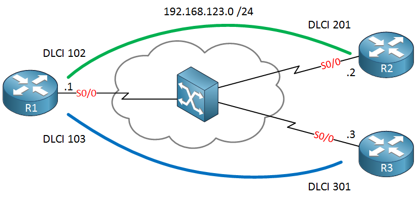
Using multipoint frame-relay means that we will use a single subnet for all PVCs. I will use 192.168.123.0 /24 for our routers, you can see it in the diagram below:
Physical interfaces that use frame-relay encapsulation are multipoint by default. Inverse ARP is also enabled by default so once you configure IP addresses on your interfaces then you should see some frame-relay maps:
R1#show frame-relay map
Serial0/0 (up): ip 192.168.123.2 dlci 102(0x66,0x1860), dynamic,
              broadcast,, status defined, active
Serial0/0 (up): ip 192.168.123.3 dlci 103(0x67,0x1870), dynamic,
broadcast,, status defined, activeR2#show frame-relay map
Serial0/0 (up): ip 192.168.123.1 dlci 201(0xC9,0x3090), dynamic,
broadcast,, status defined, activeR3#show frame-relay map
Serial0/0 (up): ip 192.168.123.1 dlci 301(0x12D,0x48D0), dynamic,
broadcast,, status defined, activeTake a close look at the output above. You can see that R1 knows how to reach R2 and R3 and these two routers also know how to reach R1. The dynamic parameter tells us that these entries were created by inverse ARP. The broadcast parameter tells us that we can send broadcast and multicast traffic.
Everything looks ok so let’s configure EIGRP:
R1, R2 & R3#
(config)#router eigrp 123
(config-router)#no auto-summary
(config-router)#network 192.168.123.0I’ll use the same network command on all routers, after a few seconds they will be neighbors:
R1#show ip eigrp neighbors
IP-EIGRP neighbors for process 123
H Address Interface Hold Uptime SRTT RTO Q Seq
(sec) (ms) Cnt Num
1 192.168.123.3 Se0/0 170 00:10:35 44 264 0 3
0 192.168.123.2 Se0/0 146 00:10:43 1253 5000 0 3So far so good, R1 sees two neighbors but we are not done yet. Let’s try to advertise something in EIGRP. I’ll create a new loopback interface on R2 and will advertise it in EIGRP:
R2(config)#interface loopback 0
R2(config-if)#ip address 2.2.2.2 255.255.255.0
R2(config)#router eigrp 123
R2(config-router)#network 2.2.2.0 0.0.0.255Now let’s see if R1 and R3 learn this network:
R1#show ip route eigrp
2.0.0.0/24 is subnetted, 1 subnets
D 2.2.2.0 [90/2297856] via 192.168.123.2, 00:01:06, Serial0/0R1 knows about it, no issues there. What about R3?
R3#show ip route eigrp
R3 doesn’t have anything in its routing table. Why not? This is because split horizon is enabled by default. Anything that R1 learns on its serial 0/0 interface will not be advertised out of the same interface. Let’s disable it:
R1(config)#interface serial 0/0
R1(config-if)#no ip split-horizon eigrp 123Let’s see if this makes any difference:
R3#show ip route eigrp
2.0.0.0/24 is subnetted, 1 subnets
D 2.2.2.0 [90/2809856] via 192.168.123.1, 00:00:22, Serial0/0There we go, R3 has it in its routing table. Are we done now? There’s still one issue we have to deal with…take a look at this ping:
R3#ping 2.2.2.2
Type escape sequence to abort.
Sending 5, 100-byte ICMP Echos to 2.2.2.2, timeout is 2 seconds:
.....
Success rate is 0 percent (0/5)R3 is unable to ping 2.2.2.2 even though it has an entry in the routing table. Let’s find out what is going on here. First we’ll check R3:
R3#show ip route 2.2.2.2
Routing entry for 2.2.2.0/24
Known via "eigrp 123", distance 90, metric 2809856, type internal
Redistributing via eigrp 123
Last update from 192.168.123.1 on Serial0/0, 00:02:59 ago
Routing Descriptor Blocks:
* 192.168.123.1, from 192.168.123.1, 00:02:59 ago, via Serial0/0
Route metric is 2809856, traffic share count is 1
Total delay is 45000 microseconds, minimum bandwidth is 1544 Kbit
Reliability 255/255, minimum MTU 1500 bytes
Loading 1/255, Hops 2R3 is not the issue. It knows that it can reach 2.2.2.2 by sending packets to 192.168.123.1. R3 has a frame-relay map to reach this IP address:
R3#show frame-relay map
Serial0/0 (up): ip 192.168.123.1 dlci 301(0x12D,0x48D0), dynamic,
broadcast,, status defined, activeLet’s check R1, it won’t hurt to try a ping:
R1#ping 2.2.2.2
Type escape sequence to abort.
Sending 5, 100-byte ICMP Echos to 2.2.2.2, timeout is 2 seconds:
!!!!!
Success rate is 100 percent (5/5), round-trip min/avg/max = 8/20/56 msNow we know that R3 knows how to reach 2.2.2.2 and R1 is able to ping it. Our ping from R3 is able to make it to R2 so it’s probably the return traffic that is failing. Let’s take a look at R2:
R2#show ip route 192.168.123.0
Routing entry for 192.168.123.0/24
Known via "connected", distance 0, metric 0 (connected, via interface)
Redistributing via eigrp 123
Routing Descriptor Blocks:
* directly connected, via Serial0/0
Route metric is 0, traffic share count is 1On R2 you can see that 192.168.123.0 /24 is a directly connected network. That’s great but when we look at the frame-relay maps we only see one entry:
R2#show frame-relay map
Serial0/0 (up): ip 192.168.123.1 dlci 201(0xC9,0x3090), dynamic,
broadcast,, status defined, activeR2 doesn’t know how to reach 192.168.123.3, there’s only an entry for R1. Let’s create this entry ourselves:
R2(config-if)#frame-relay map ip 192.168.123.3 201From now on, R2 knows that 192.168.123.3 is reachable through DLCI 201. We can verify this:
R2#show frame-relay map
Serial0/0 (up): ip 192.168.123.3 dlci 201(0xC9,0x3090), static,
              CISCO, status defined, active
Serial0/0 (up): ip 192.168.123.1 dlci 201(0xC9,0x3090), dynamic,
              broadcast,, status defined, active
Let’s try that ping from R3 again:
R3#ping 2.2.2.2

Type escape sequence to abort.
Sending 5, 100-byte ICMP Echos to 2.2.2.2, timeout is 2 seconds:
!!!!!
Success rate is 100 percent (5/5), round-trip min/avg/max = 1/15/40 ms
Our ping is now working, problem solved!
Our multipoint scenario is now finished.
Configurations
Want to take a look for yourself? Here you will find the final configuration of each device.
R1
hostname R1
!
interface Serial0/0
 ip address 192.168.123.1 255.255.255.0
 no ip split-horizon eigrp 123
 encapsulation frame-relay
 clock rate 2000000
!
router eigrp 123
 no auto-summary
 network 192.168.123.0
!
end
R2
hostname R2
!
interface Serial0/0
 ip address 192.168.123.2 255.255.255.0
 frame-relay map ip 192.168.123.3 201
!
interface loopback 0
 ip address 2.2.2.2 255.255.255.0
!
router eigrp 123
 no auto-summary
 network 192.168.123.0
 network 2.2.2.0 0.0.0.255
!
end
R3
hostname R3
!
interface Serial0/0
 ip address 192.168.123.3 255.255.255.0
!
router eigrp 123
 no auto-summary
 network 192.168.123.0
!
end
There’s one thing left to discuss and that’s the sub-interface. Physical interfaces running frame-relay are always multipoint interfaces but if you want you can also use a sub-interface. Let me show you the current interface configuration:
R1#show run interface serial 0/0
Building configuration...

Current configuration : 145 bytes
!
interface Serial0/0
 ip address 192.168.123.1 255.255.255.0
 encapsulation frame-relay
 no ip split-horizon eigrp 123
 clock rate 2000000
end
We will move the configuration above from the physical interface to a sub-interface. Let’s reset it first:
R1(config)#default interface serial 0/0
Building configuration...
Our physical interface only requires one or two commands. You need to enable frame-relay encapsulation and if you are the DCE side you’ll have to set the clock rate:
R1(config)#interface serial 0/0
R1(config-if)#encapsulation frame-relay
R1(config-if)#clock rate 2000000
Now we can create the sub-interface:
R1(config)#interface serial 0/0.123 ?
  multipoint      Treat as a multipoint link
  point-to-point  Treat as a point-to-point link
You can choose between multipoint or point-to-point, let’s choose multipoint:
R1(config)#interface serial 0/0.123 multipoint
R1(config-subif)#ip address 192.168.123.1 255.255.255.0
R1(config-subif)#no ip split-horizon eigrp 123
R1(config-subif)#frame-relay interface-dlci 102
R1(config-subif)#frame-relay interface-dlci 103
On the sub-interface we will configure the IP address and we will disable EIGRP split horizon. By default our DLCI numbers will be “attached” to the physical interface. Since we are now using a sub-interface we have to tell the router that the DLCI numbers belong to this sub-interface.
After making these changes you can verify that the frame-relay maps have been updated:
R1#show frame-relay map
Serial0/0.123 (up): ip 192.168.123.2 dlci 102(0x66,0x1860), dynamic,
              broadcast,, status defined, active
Serial0/0.123 (up): ip 192.168.123.3 dlci 103(0x67,0x1870), dynamic,
              broadcast,, status defined, active
You can also see that EIGRP now has neighbors on the sub-interface:
R1#show ip eigrp neighbors
IP-EIGRP neighbors for process 123
H   Address                 Interface       Hold Uptime   SRTT   RTO  Q  Seq
                                            (sec)         (ms)       Cnt Num
1   192.168.123.3           Se0/0.123         13 00:01:53   32   200  0  20
0   192.168.123.2           Se0/0.123         13 00:01:58   43   258  0  16
That’s all there is to tell about multipoint interfaces. You have to be aware of split horizon issues and missing frame-relay maps for spoke-to-spoke traffic.
Configurations
Want to take a look for yourself? Here you will find the startup configuration of each device.
R1
hostname R1
!
interface Serial0/0
encapsulation frame-relay
clock rate 2000000
!
interface serial 0/0.123 multipoint
ip address 192.168.123.1 255.255.255.0
no ip split-horizon eigrp 123
frame-relay interface-dlci 102
frame-relay interface-dlci 103
!
router eigrp 123
no auto-summary
network 192.168.123.0
!
end
R2
hostname R2
!
interface Serial0/0
 encapsulation frame-relay
 ip address 192.168.123.2 255.255.255.0
 frame-relay map ip 192.168.123.3 201
!
interface loopback 0
 ip address 2.2.2.2 255.255.255.0
!
router eigrp 123
 no auto-summary
 network 192.168.123.0
 network 2.2.2.0 0.0.0.255
!
end
R3
hostname R3
!
interface Serial0/0
 encapsulation frame-relay
 ip address 192.168.123.3 255.255.255.0
 frame-relay map ip 192.168.123.2 301
!
router eigrp 123
 no auto-summary
 network 192.168.123.0
!
end
Let’s take a look at the point-to-point scenario now.
EIGRP on Point-to-Point Frame-Relay
Using point-to-point sub-interfaces on a frame-relay network makes your life a lot easier, this configuration is straight-forward and works without any issues. Let me show you the topology again:
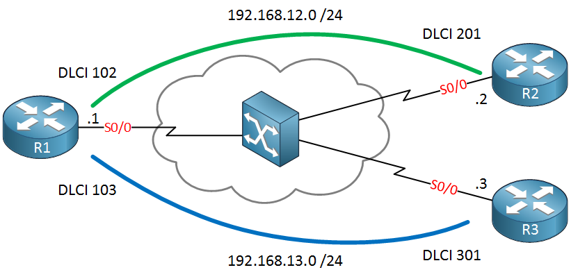
The topology doesn’t change but this time we use a different subnet for each PVC. Let’s start with a clean configuration:
R1#show running-config interface serial 0/0
Building configuration...

Current configuration : 89 bytes
!
interface Serial0/0
 no ip address
 encapsulation frame-relay
 clock rate 2000000
Our physical interface is using frame-relay but that’s it. Let’s see if the PVCs are active:
R1#show frame-relay pvc | include DLCI
DLCI = 102, DLCI USAGE = LOCAL, PVC STATUS = ACTIVE, INTERFACE = Serial0/0
DLCI = 103, DLCI USAGE = LOCAL, PVC STATUS = ACTIVE, INTERFACE = Serial0/0R2#show frame-relay pvc | include DLCI
DLCI = 201, DLCI USAGE = LOCAL, PVC STATUS = ACTIVE, INTERFACE = Serial0/0R3#show frame-relay pvc | include DLCI
DLCI = 301, DLCI USAGE = LOCAL, PVC STATUS = ACTIVE, INTERFACE = Serial0/0No issues there, layer 2 is up and running. Let’s configure some sub-interfaces on R1:
R1(config)#interface serial 0/0.12 point-to-point
R1(config-subif)#ip address 192.168.12.1 255.255.255.0
R1(config-subif)#frame-relay interface-dlci 102

R1(config)#interface serial 0/0.13 point-to-point
R1(config-subif)#ip address 192.168.13.1 255.255.255.0
R1(config-subif)#frame-relay interface-dlci 103
Above you can see that we have a sub-interface for each PVC. The only thing you have to do is add an IP address and tell the router which DLCI number belongs to the sub-interface. Let’s do the same thing on R2 and R3:
R2(config)#interface serial 0/0.12 point-to-point
R2(config-subif)#ip address 192.168.12.2 255.255.255.0
R2(config-subif)#frame-relay interface-dlci 201R3(config)#interface serial 0/0.13 point-to-point
R3(config-subif)#ip address 192.168.13.3 255.255.255.0
R3(config-subif)#frame-relay interface-dlci 301That’s all there is to it. Let’s try a quick ping on R1 to make sure that layer 2 and 3 are up and running:
R1#ping 192.168.12.2

Type escape sequence to abort.
Sending 5, 100-byte ICMP Echos to 192.168.12.2, timeout is 2 seconds:
!!!!!
Success rate is 100 percent (5/5), round-trip min/avg/max = 8/16/28 msR1#ping 192.168.13.3
Type escape sequence to abort.
Sending 5, 100-byte ICMP Echos to 192.168.13.3, timeout is 2 seconds:
!!!!!
Success rate is 100 percent (5/5), round-trip min/avg/max = 4/20/36 msOur pings are working. Let’s configure EIGRP:
R1(config)#router eigrp 123
R1(config-router)#no auto-summary
R1(config-router)#network 192.168.12.0
R1(config-router)#network 192.168.13.0R2(config)#router eigrp 123
R2(config-router)#no auto-summary
R2(config-router)#network 192.168.12.0
R2(config-router)#network 2.2.2.0 0.0.0.255R3(config-subif)#router eigrp 123
R3(config-router)#no auto-summary
R3(config-router)#network 192.168.13.0I activated EIGRP on all sub-interfaces, note that I also advertised the loopback interface from the previous example as well. Let’s see if R1 has any neighbors:
R1#show ip eigrp neighbors
IP-EIGRP neighbors for process 123
H   Address                 Interface       Hold Uptime   SRTT   RTO  Q  Seq
                                            (sec)         (ms)       Cnt Num
1   192.168.13.3            Se0/0.13          14 00:00:28   48   432  0  15
0   192.168.12.2            Se0/0.12          10 00:00:59   43   258  0  12
R1 has two neighbors, we reach R3 on serial0/0.13 and R2 on serial0/0.12.
Let’s check the routing tables:
R3#show ip route eigrp
D    192.168.12.0/24 [90/2681856] via 192.168.13.1, 00:01:54, Serial0/0.13
     2.0.0.0/24 is subnetted, 1 subnets
D 2.2.2.0 [90/2809856] via 192.168.13.1, 00:01:54, Serial0/0.13R2#show ip route eigrp
D 192.168.13.0/24 [90/2681856] via 192.168.12.1, 00:02:40, Serial0/0.12You can see that the spoke routers learn about each others networks (192.168.12.0 /24 and 192.168.13.0 /24). R3 also learns how to reach 2.2.2.0 /24.
Let’s try a quick ping:
Hi Rene,
Can we use “frame-relay interface-dlci DLCI NUMBER” command in frame-relay multipoint connection ?
You could yes, basically all the command does is say “this DLCI number belongs to this interface”.
So how dose the interface map between IP address and dlci number since we have tow router on the same subnet on the other side ?
Inverse ARP will take care of that. If you use “frame-relay interface DLCI” on a multipoint sub-interface then it will work.
Thanks Rene,
Now it’s clear.