Lesson Contents
VXLAN MP-BGP EVPN allows you to bridge traffic over the VXLAN fabric but can also route traffic. This can be useful when you have multiple VNIs with different subnets behind your VTEPs. You’ll have all the advantages of VXLAN, such as having a large number (~16 million unique VNIs) of isolated networks because of the 24-bit identifier for VNI and using overlay networking.
With L2 VNIs, it is simple. Your hosts are in a single VLAN and mapped to a VNI. The leaf switches bridge this traffic and don’t have to route anything. We call this intra-VNI traffic. The traffic remains within the VNI. If you are unsure how L2 VNIs work, start with the L2 VNI lesson; otherwise, this lesson will be difficult to follow.
What if we have two hosts in different VLANs and subnets? Each VLAN will be mapped to a different VNI. Take a look at this picture:
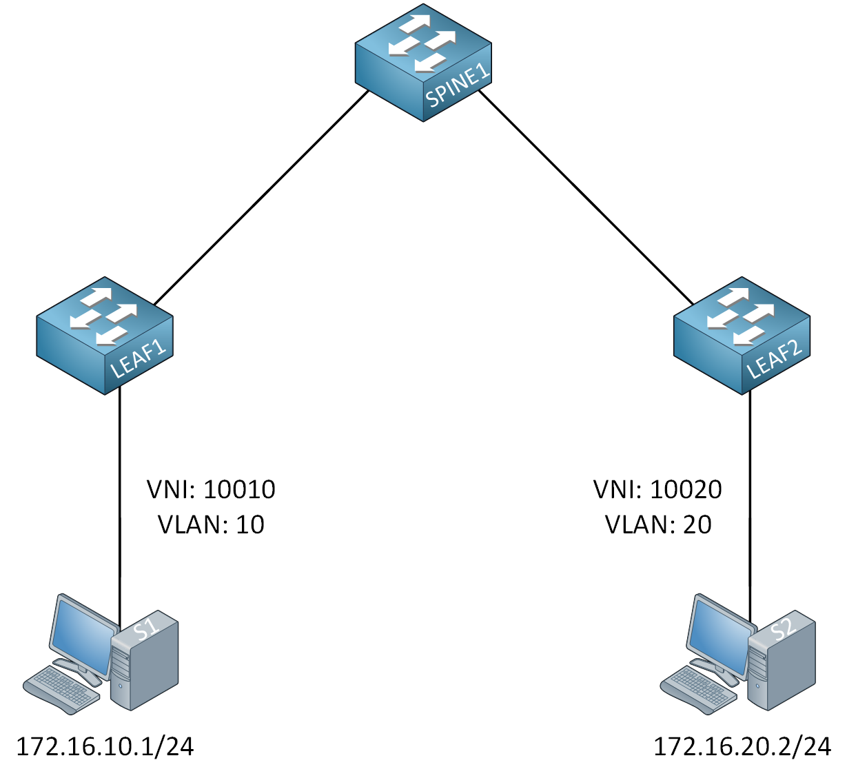
Host S1 is in 172.16.10.0/24, and S2 is in 172.16.20.0/24. Because we use different subnets, we need to route this traffic. We call this inter-VNI traffic, and our VTEPs can do it.
L3 VNI is not too difficult to configure, but you need to understand the logic of how the VTEP bridges and routes traffic. This is best explained with a picture, so take a look below:
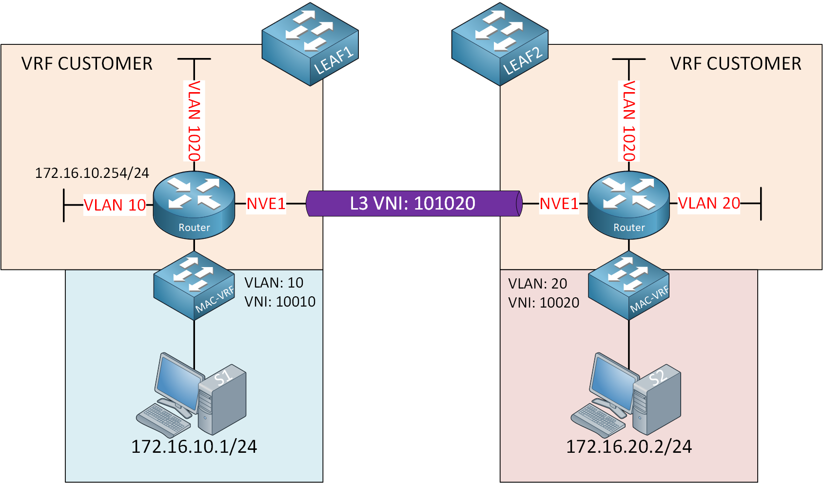
Let me break down what we have here:
- We have two leaf switches (connected through a spine switch not shown here).
- The leaf switches perform bridging and routing. I visualized this by adding a router and switch icon.
- Leaf switches advertise the subnets they know about through MP-BGP EVPN:
- 172.16.10.0/24 on LEAF1.
- 172.16.20.0/24 on LEAF2.
- We have two hosts:
- S1 connected to LEAF1:
- VLAN 10
- VNI 10010
- 172.16.10.1/24
- S2 connected to LEAF2:
- VLAN 20
- VNI 10020
- 172.16.20.2/24
- S1 connected to LEAF1:
- The hosts use the IP address on the corresponding SVI interface of the LEAF switches:
- S1 uses 172.16.10.254/24 for VLAN 10.
- S2 uses 172.16.20.254/24 for VLAN 20.
- This allows the hosts to get outside of their subnet.
The hosts can reach the default gateways of the leaf switches, but how do we get from LEAF1 to LEAF2 across the VXLAN fabric? To accomplish this, we create a new VLAN and VNI that is the same on both leaf switches and can be used for inter-VNI routing. We’ll use VLAN 1020 and VNI 101020 for this. This is for transit traffic between the two leaf switches.
Also, in our picture, we only have one customer, but with multitenancy, you want to separate your routing between tenants. This is why we use a VRF. We’ll use VRF CUSTOMER. Let’s see what happens when S1 sends a packet to S2:
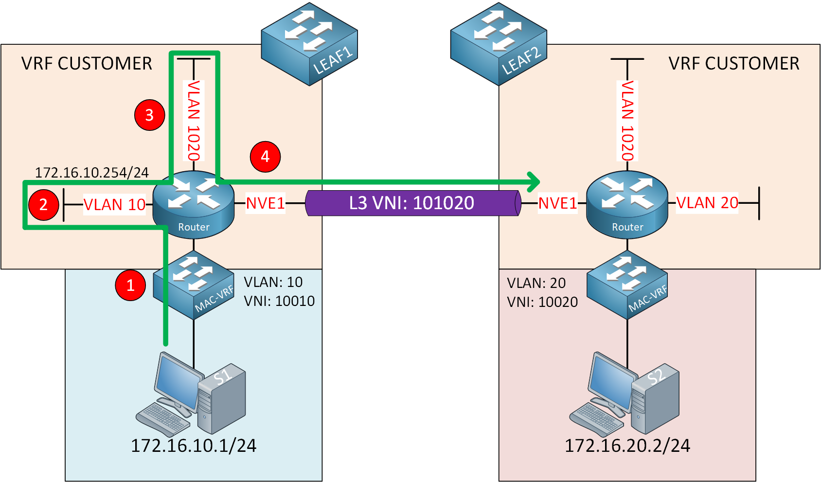
Let me break this down step-by-step:
- S1 sends a packet destined for S2, and LEAF1 bridges this packet in VLAN 10 using L2 VNI 10010.
- The packet ends up at the default gateway in VLAN 10 (172.16.10.254).
- LEAF1 does a routing lookup for 172.16.20.0/24 and uses the VLAN 1020 SVI interface for routing.
- LEAF1 encapsulates the packet with VXLAN and transmits it using the NVE interface.
Configuration
Let’s see if we can make this work. This is the topology we’ll use:
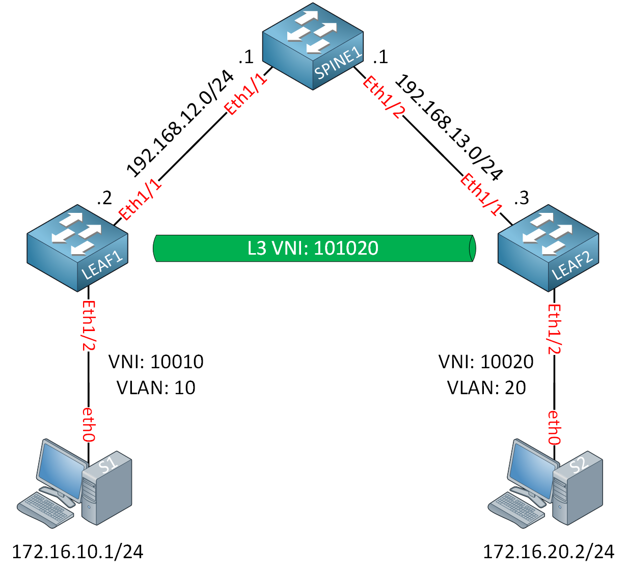
I’m using Cisco Nexus 9300v switches running version 9.3(9). The hosts are Ubuntu Docker containers. The spine switch is the BGP route reflector. I configured the underlay network with OSPF and the spine switch as the RP. Technically, we don’t need multicast in the underlay network because we’ll only have inter-VNI traffic. We don’t have intra-VNI traffic between hosts within an L2 VNI. Because of this, I didn’t configure PIM on the switches.
Configurations
Want to take a look for yourself? Here, you will find the startup configuration of each device.
LEAF1
hostname LEAF1

feature ospf

interface Ethernet1/1
  no switchport
  mac-address 0050.c253.2001
  ip address 192.168.12.2/24
  ip ospf network point-to-point
  ip router ospf 1 area 0.0.0.0
  no shutdown

interface Ethernet1/2
  switchport access vlan 10

interface loopback0
  ip address 2.2.2.2/32
  ip router ospf 1 area 0.0.0.0

router ospf 1
LEAF2
hostname LEAF2

feature ospf

interface Ethernet1/1
  no switchport
  mac-address 0050.c253.3001
  ip address 192.168.13.3/24
  ip ospf network point-to-point
  ip router ospf 1 area 0.0.0.0
  no shutdown

interface Ethernet1/2
  switchport access vlan 20

interface loopback0
  ip address 3.3.3.3/32
  ip router ospf 1 area 0.0.0.0

router ospf 1
SPINE1
hostname SPINE1

feature ospf

interface Ethernet1/1
  no switchport
  mac-address 0050.c253.1001
  ip address 192.168.12.1/24
  ip ospf network point-to-point
  ip router ospf 1 area 0.0.0.0
  no shutdown

interface Ethernet1/2
  no switchport
  mac-address 0050.c253.1002
  ip address 192.168.13.1/24
  ip ospf network point-to-point
  ip router ospf 1 area 0.0.0.0
  no shutdown

interface loopback0
  ip address 1.1.1.1/32
  ip router ospf 1 area 0.0.0.0

router ospf 1
Here are the key components we need to configure:
- Create a VRF for our customer for inter-VNI traffic.
- Create the VLAN and L3 VNI for traffic between the leaf switches.
- Create the SVI interface for L3 VNI.
- Configure the VLAN, VNI, and SVI for the hosts.
- Configure MP-BGP EVPN and advertise the subnets the leaf switches learn.
SPINE1
Let’s start with the SPINE1 switch config. This is straightforward and the same as what we did in the L2 VNI lesson. We configure this switch to be the BGP RR with LEAF1 and LEAF2 as clients:
SPINE1(config)# feature bgp
SPINE1(config)# nv overlay evpn
SPINE1(config)# router bgp 123
SPINE1(config-router)# neighbor 2.2.2.2
SPINE1(config-router-neighbor)# remote-as 123
SPINE1(config-router-neighbor)# update-source loopback0
SPINE1(config-router-neighbor)# address-family l2vpn evpn
SPINE1(config-router-neighbor-af)# send-community
SPINE1(config-router-neighbor-af)# send-community extended
SPINE1(config-router-neighbor-af)# route-reflector-client
SPINE1(config-router)# neighbor 3.3.3.3
SPINE1(config-router-neighbor)# remote-as 123
SPINE1(config-router-neighbor)# update-source loopback0
SPINE1(config-router-neighbor)# address-family l2vpn evpn
SPINE1(config-router-neighbor-af)# send-community
SPINE1(config-router-neighbor-af)# send-community extended
SPINE1(config-router-neighbor-af)# route-reflector-clientThat’s all we need.
LEAF1
Let’s continue with the leaf switches. We’ll start with LEAF1. We’ll start with the VRF for our customer. Make sure you enable this feature:
LEAF1(config)# feature vn-segment-vlan-basedNow we create the VRF so we can advertise EVPN information into MP-BGP:
LEAF1(config-vrf)# vrf context CUSTOMER
LEAF1(config-vrf)# vni 101020
LEAF1(config-vrf)# address-family ipv4 unicast
We’ll use VNI 101020. Let’s create the VLAN and VNI for L3 communication:
LEAF1(config)# vlan 1020
LEAF1(config-vlan)# vn-segment 101020
We also need the SVI for inter-VNI traffic:
LEAF1(config)# feature interface-vlanLEAF1(config)# interface vlan 1020
LEAF1(config-if)# no shutdown
LEAF1(config-if)# vrf member CUSTOMER
LEAF1(config-if)# ip forwardMake sure to enable ip forward so the switch can route and encapsulate/decapsulate VXLAN packets.
Now we’ll create the VLAN and VNI for host S1:
LEAF1(config)# vlan 10
LEAF1(config-vlan)# vn-segment 10010
And we’ll create an SVI with an IP address that S1 can use as the default gateway:
LEAF1(config)# interface vlan 10
LEAF1(config-if)# no shutdown
LEAF1(config-if)# vrf member CUSTOMER
LEAF1(config-if)# ip address 172.16.10.254/24
Let’s create the NVE interface. First, enable the required feature:
LEAF1(config)# feature nv overlayAnd create the interface:
LEAF1(config)# interface nve1
LEAF1(config-if-nve)# no shutdown
LEAF1(config-if-nve)# host-reachability protocol bgp
LEAF1(config-if-nve)# source-interface loopback0
LEAF1(config-if-nve)# member vni 10010
LEAF1(config-if-nve-vni)# member vni 101020 associate-vrf
The last command is new. We associate the L3 VNI with the L2 VNI here.
The last part is to configure BGP. The first part is the same. We enable the required features:
LEAF1(config)# feature bgp
LEAF1(config)# nv overlay evpn
And we’ll configure SPINE1 as our neighbor:
LEAF1(config)# router bgp 123
LEAF1(config-router)# neighbor 1.1.1.1
LEAF1(config-router-neighbor)# remote-as 123
LEAF1(config-router-neighbor)# update-source loopback0
LEAF1(config-router-neighbor)# address-family l2vpn evpn
LEAF1(config-router-neighbor-af)# send-community
LEAF1(config-router-neighbor-af)# send-community extended

LEAF1(config-router)# vrf CUSTOMER
LEAF1(config-router-vrf)# address-family ipv4 unicast
LEAF1(config-router-vrf-af)# network 172.16.10.0/24
The last part is new. Under the VRF, we advertise network 172.16.10.0/24 so that SPINE1 and LEAF2 can learn about it.
LEAF2
The configuration of LEAF2 is the same, except we use VLAN 20 and subnet 172.16.20.0/24. Let’s create the VRF for inter-VNI traffic:
LEAF2(config)# feature vn-segment-vlan-basedLEAF2(config)# vrf context CUSTOMER
LEAF2(config-vrf)# vni 101020
LEAF2(config-vrf)# address-family ipv4 unicastWe’ll create the matching VLAN:
LEAF2(config)# vlan 1020
LEAF2(config-vlan)# vn-segment 101020
The SVI for L3 VNI:
LEAF2(config)# feature interface-vlanLEAF2(config)# interface vlan 1020
LEAF2(config-if)# no shutdown
LEAF2(config-if)# vrf member CUSTOMER
LEAF2(config-if)# ip forwardThe customer VLAN and L2 VNI:
LEAF2(config)# vlan 20
LEAF2(config-vlan)# vn-segment 10020
The SVI that S2 can use as the default gateway:
LEAF2(config)# interface vlan 20
LEAF2(config-if)# no shutdown
LEAF2(config-if)# vrf member CUSTOMER
LEAF2(config-if)# ip address 172.16.20.254/24
The NVI interface:
LEAF2(config)# feature nv overlayLEAF2(config)# interface nve1
LEAF2(config-if-nve)# no shutdown
LEAF2(config-if-nve)# host-reachability protocol bgp
LEAF2(config-if-nve)# source-interface loopback0
LEAF2(config-if-nve)# member vni 10020
LEAF2(config-if-nve-vni)# member vni 101020 associate-vrfAnd finally, the MP-BGP EVPN configuration:
LEAF2(config)# feature bgp
LEAF2(config)# nv overlay evpn
LEAF2(config)# router bgp 123
LEAF2(config-router)# neighbor 1.1.1.1
LEAF2(config-router-neighbor)# remote-as 123
LEAF2(config-router-neighbor)# update-source loopback0
LEAF2(config-router-neighbor)# address-family l2vpn evpn
LEAF2(config-router-neighbor-af)# send-community
LEAF2(config-router-neighbor-af)# send-community extended
LEAF2(config-router)# vrf CUSTOMER
LEAF2(config-router-vrf)# address-family ipv4 unicast
LEAF2(config-router-vrf-af)# network 172.16.20.0/24That completes our configuration.
Verification
Let’s find out if everything is working. First, we’ll check the SVI interfaces:
LEAF1# show ip int brief vrf CUSTOMER

IP Interface Status for VRF "CUSTOMER"(3)
Interface            IP Address      Interface Status
Vlan10               172.16.10.254   protocol-up/link-up/admin-up
Vlan1020             forward-enabled protocol-up/link-up/admin-up
The SVI for VLAN 10 has an IP address, and the SVI for L3 inter-VNI traffic has forwarding enabled. Let’s check the NVE interface:
Can you explain this but using 2 or more spine switches?
Hello Dimas
The configuration doesn’t change much if you add more spine switches. The Leaf switch configurations remain the same. If you have two or more spine switches, you simply have to ensure that you have configured EVPN as the overlay, and that you have configured BGP using the L2VPN EVPN address family. As long as BGP has converged, your network will function.
This is an excellent exercise that you can try out in an emulator. It will definitely help you to gain a deeper understanding of the intricacies involved in VXLAN MP-BGP EVPN configurations. I
... Continue reading in our forumYou can also use this topology:
https://networklessons.com/vxlan/vxlan-multicast-anycast-rp
I’m breaking down the different VXLAN topics into separate examples. If we only need one spine switch to explain a topic, I’ll use one. We’ll add more complex topologies where we combine different topics later.
Rene
Sholdn’t be member vni 10020 under nve on Leaf2 config? 10010 is written.
Hello Funda
You are correct. Under the final configurations for each device, the
member vnicommand should show a value of 10020 and not 10010 as is indicated. The values are correct in the lesson, but not inthe final config. I will let Rene know to make the correction.Thanks for pointing that out!
Laz