Lesson Contents
In the VXLAN Flood and Learn Multicast Data Plane lesson, we configured VXLAN flood and learn using multicast. This worked, but we had a single spine switch configured as the static Rendezvous Point (RP). If you don’t want a single point of failure, you can add a second spine switch. This introduces another issue: which spine switch should be the RP?
You can configure RP redundancy with protocols like auto-RP or bootstrap. However, failover for these protocols is not very fast.
Another option is anycast RP. This is a technique where multiple devices act as a single RP using the same IP address. However, this also introduces an issue. Leaf switches have two uplinks, one to each spine switch. It’s possible that some leaf switches join one spine switch, and others join the second spine switch. This is not random; we use a hashing algorithm to decide which uplink to use:
LEAF1# show ip multicast vrf default
Multicast Routing VRFs (1 VRFs)
VRF Name              VRF      Table       Route   Group   Source  (*,G)   State
                      ID       ID          Count   Count   Count   Count

default               1        0x00000001  3       1       1       1       Up
    Multipath configuration (1): s-g-hash
    Resilient configuration: Disabled
ECMP multicast uses the s-g-hash based on the source and group address. This hashing algorithm is predictable because it does not use random values.
We need something that can synchronize information between RPs. There are two protocols we can use for this:
Cisco Nexus switches can use anycast RP without MSDP. PIM messages will be exchanged between spine switches so all spine switches know about the multicast sources. In this lesson, I’ll explain how to configure anycast RP and we’ll do a packet capture to see it in action.
Configuration
This is the topology we’ll use:
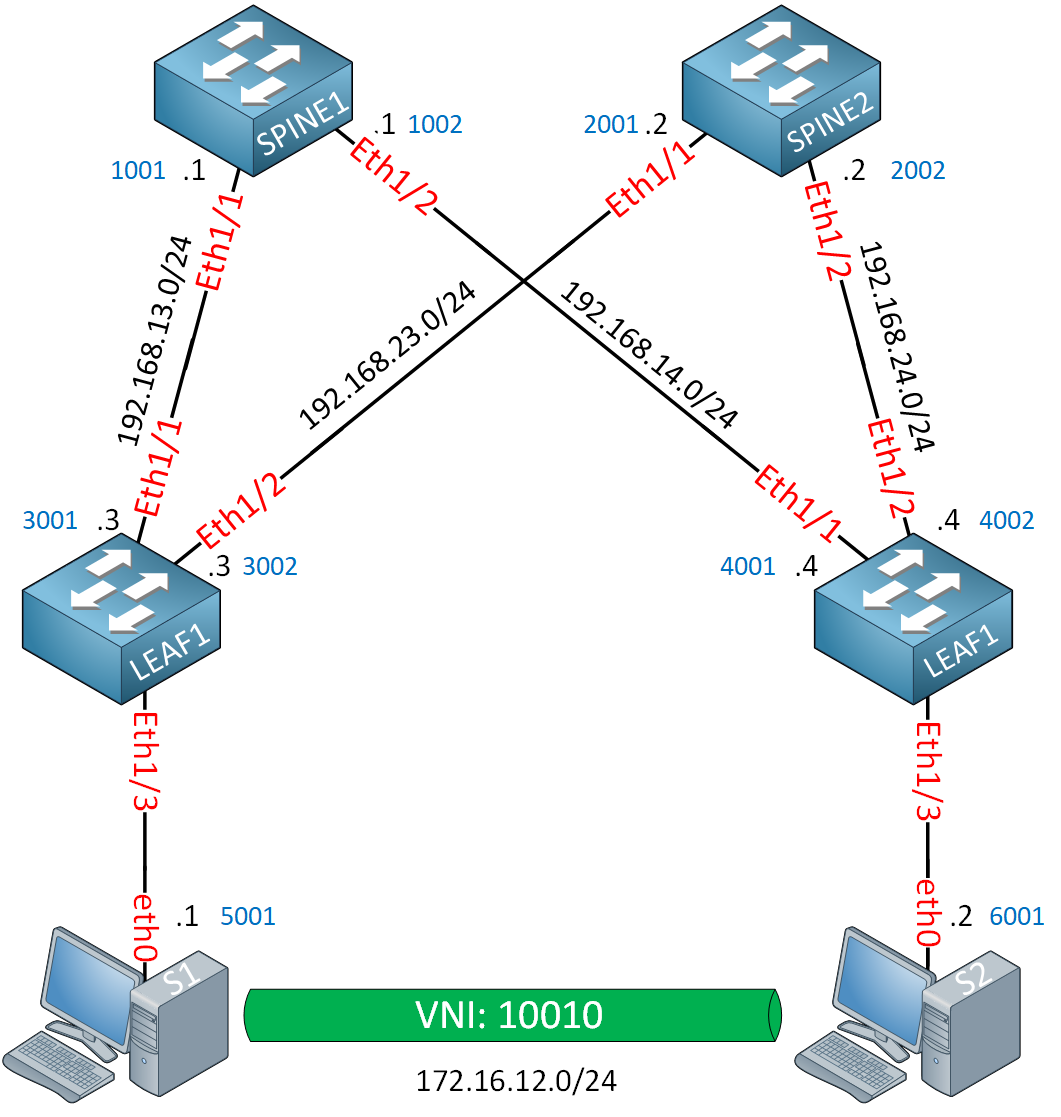
We’ll need two spine switches. I’m using Cisco NX-OS 9000v version 9.3(9) on the switches. The hosts (S1 and S2) are simple Ubuntu containers because they only need to send some ICMP traffic between each other.
I use static MAC addresses on all devices so that it’s easier to debug and do a packet capture. All MAC addresses look like 0050.c253.X00Y, where X is the device number and Y is the interface number.
Also, since we already configured the underlay and overlay in the VXLAN flood and learn multicast lesson, I’m focusing only on the configuration of anycast RP in this lesson. We start with a pre-configured underlay/overlay network.
Configurations
Want to take a look for yourself? Here, you will find the startup configuration of each device. You can also download the containerlab topology.
LEAF1
hostname LEAF1

feature ospf
feature pim
feature vn-segment-vlan-based
feature nv overlay

vlan 10
  vn-segment 10010

interface nve1
  no shutdown
  source-interface loopback0
  member vni 10010
    mcast-group 239.1.1.1

interface Ethernet1/1
  no switchport
  mac-address 0050.c253.3001
  ip address 192.168.13.3/24
  ip ospf network point-to-point
  ip router ospf 1 area 0.0.0.0
  ip pim sparse-mode
  no shutdown

interface Ethernet1/2
  no switchport
  mac-address 0050.c253.3002
  ip address 192.168.23.3/24
  ip ospf network point-to-point
  ip router ospf 1 area 0.0.0.0
  ip pim sparse-mode
  no shutdown

interface Ethernet1/3
  no shutdown
  switchport access vlan 10

interface loopback0
  ip address 3.3.3.3/32
  ip router ospf 1 area 0.0.0.0
  ip pim sparse-mode

router ospf 1
LEAF2
hostname LEAF2

feature ospf
feature pim
feature vn-segment-vlan-based
feature nv overlay

vlan 10
  vn-segment 10010

interface nve1
  no shutdown
  source-interface loopback0
  member vni 10010
    mcast-group 239.1.1.1

interface Ethernet1/1
  no switchport
  mac-address 0050.c253.4001
  ip address 192.168.14.4/24
  ip ospf network point-to-point
  ip router ospf 1 area 0.0.0.0
  ip pim sparse-mode
  no shutdown

interface Ethernet1/2
  no switchport
  mac-address 0050.c253.4002
  ip address 192.168.24.4/24
  ip ospf network point-to-point
  ip router ospf 1 area 0.0.0.0
  ip pim sparse-mode
  no shutdown

interface Ethernet1/3
  no shutdown
  switchport access vlan 10

interface loopback0
  ip address 4.4.4.4/32
  ip router ospf 1 area 0.0.0.0
  ip pim sparse-mode

router ospf 1
SPINE1
hostname SPINE1

feature ospf
feature pim

interface Ethernet1/1
  no switchport
  mac-address 0050.c253.1001
  ip address 192.168.13.1/24
  ip ospf network point-to-point
  ip router ospf 1 area 0.0.0.0
  ip pim sparse-mode
  no shutdown

interface Ethernet1/2
  no switchport
  mac-address 0050.c253.1002
  ip address 192.168.14.1/24
  ip ospf network point-to-point
  ip router ospf 1 area 0.0.0.0
  ip pim sparse-mode
  no shutdown

interface loopback0
  ip address 1.1.1.1/32
  ip router ospf 1 area 0.0.0.0
  ip pim sparse-mode

router ospf 1
SPINE2
hostname SPINE2

feature ospf
feature pim

interface Ethernet1/1
  no switchport
  mac-address 0050.c253.2001
  ip address 192.168.23.2/24
  ip ospf network point-to-point
  ip router ospf 1 area 0.0.0.0
  ip pim sparse-mode
  no shutdown

interface Ethernet1/2
  no switchport
  mac-address 0050.c253.2002
  ip address 192.168.24.2/24
  ip ospf network point-to-point
  ip router ospf 1 area 0.0.0.0
  ip pim sparse-mode
  no shutdown

interface loopback0
  ip address 2.2.2.2/32
  ip router ospf 1 area 0.0.0.0
  ip pim sparse-mode

router ospf 1
The configuration is almost identical to when we used multicast with a single RP. To configure anycast RP, we need to do this:
- Create a new loopback interface on the spine switches with the IP address we want to use for anycast RP.
- Enable OSPF on this loopback.
- Enable PIM on this loopback.
- Configure the spine switches to use the IP address on the new loopback interface as RP.
- Configure all IP addresses of the spine switches for the anycast RP set.
- Configure all switches to use the anycast RP address.
This is what anycast RP looks like on the spine switches:
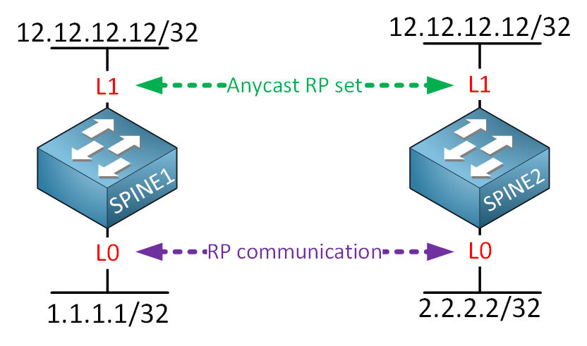
We’ll use 12.12.12.12 as the RP address. The spine switches still need a unique IP address on their loopback 0 interfaces because they use this to communicate with each other.
Let’s get started:
SPINE1 & SPINE2
(config)# interface loopback1
(config-if)# ip address 12.12.12.12/32
(config-if)# ip router ospf 1 area 0.0.0.0
(config-if)# ip pim sparse-mode
Now we configure the RP set:
SPINE1 & SPINE2
(config)# ip pim anycast-rp 12.12.12.12 1.1.1.1
(config)# ip pim anycast-rp 12.12.12.12 2.2.2.2
On both spine switches, we need to configure:
- the IP address we want to use for anycast RP.
- Our own IP address.
- The IP address of the other spine switch.
On all switches, we configure 12.12.12.12 as the RP:
SPINE1, SPINE2, LEAF1 & LEAF2
(config)# ip pim rp-address 12.12.12.12
That’s all we need to do.
Verification
Let’s make sure we have PIM neighbors:
SPINE1# show ip pim neighbor
PIM Neighbor Status for VRF "default"
Neighbor        Interface            Uptime    Expires   DR       Bidir-  BFD    ECMP Redirect
                                                         Priority Capable State     Capable
192.168.13.3    Ethernet1/1          1d01h     00:01:35  1        yes     n/a     no
192.168.14.4    Ethernet1/2          1d01h     00:01:22  1        yes     n/a     no
SPINE2# show ip pim neighbor
PIM Neighbor Status for VRF "default"
Neighbor Interface Uptime Expires DR Bidir- BFD ECMP Redirect
Priority Capable State Capable
192.168.23.3 Ethernet1/1 1d01h 00:01:16 1 yes n/a no
192.168.24.4 Ethernet1/2 1d01h 00:01:43 1 yes n/a noThat seems to be the case. Let’s check the RP settings:
SPINE1# show ip pim rp
PIM RP Status Information for VRF "default"
BSR disabled
Auto-RP disabled
BSR RP Candidate policy: None
BSR RP policy: None
Auto-RP Announce policy: None
Auto-RP Discovery policy: None

Anycast-RP 12.12.12.12 members:
  1.1.1.1*  2.2.2.2

RP: 12.12.12.12*, (0),
 uptime: 1d01h   priority: 255,
 RP-source: (local),
 group ranges:
 224.0.0.0/4
SPINE2# show ip pim rp
PIM RP Status Information for VRF "default"
BSR disabled
Auto-RP disabled
BSR RP Candidate policy: None
BSR RP policy: None
Auto-RP Announce policy: None
Auto-RP Discovery policy: None
Anycast-RP 12.12.12.12 members:
2.2.2.2* 1.1.1.1
RP: 12.12.12.12*, (0),
uptime: 1d01h priority: 255,
RP-source: (local),
group ranges:
224.0.0.0/4SPINE1 and SPINE2 know about the RP address, and they know about each other. This is what the leaf switches think of it:
LEAF1# show ip pim rp
PIM RP Status Information for VRF "default"
BSR disabled
Auto-RP disabled
BSR RP Candidate policy: None
BSR RP policy: None
Auto-RP Announce policy: None
Auto-RP Discovery policy: None

RP: 12.12.12.12, (0),
 uptime: 1d01h   priority: 255,
 RP-source: (local),
 group ranges:
 224.0.0.0/4
LEAF2# show ip pim rp
PIM RP Status Information for VRF "default"
BSR disabled
Auto-RP disabled
BSR RP Candidate policy: None
BSR RP policy: None
Auto-RP Announce policy: None
Auto-RP Discovery policy: None
RP: 12.12.12.12, (0),
uptime: 1d01h priority: 255,
RP-source: (local),
group ranges:
224.0.0.0/4The leaf switches use 12.12.12.12 as the RP. Here are the multicast routing tables:
SPINE1# show ip mroute 239.1.1.1
IP Multicast Routing Table for VRF "default"

(*, 239.1.1.1/32), uptime: 00:02:59, pim ip
  Incoming interface: loopback1, RPF nbr: 12.12.12.12
  Outgoing interface list: (count: 1)
    Ethernet1/2, uptime: 00:02:59, pim


(3.3.3.3/32, 239.1.1.1/32), uptime: 00:02:34, pim mrib ip
  Incoming interface: Ethernet1/1, RPF nbr: 192.168.13.3, internal
  Outgoing interface list: (count: 1)
    Ethernet1/2, uptime: 00:02:34, pim


(4.4.4.4/32, 239.1.1.1/32), uptime: 00:02:39, pim mrib ip
  Incoming interface: Ethernet1/2, RPF nbr: 192.168.14.4, internal
  Outgoing interface list: (count: 0)
you can see LEAF1 and LEAF2 as a source for 239.1.1.1. Same thing on SPINE2:
SPINE2# show ip mroute 239.1.1.1
IP Multicast Routing Table for VRF "default"

(*, 239.1.1.1/32), uptime: 00:02:58, pim ip
  Incoming interface: loopback1, RPF nbr: 12.12.12.12
  Outgoing interface list: (count: 1)
    Ethernet1/1, uptime: 00:01:11, pim


(3.3.3.3/32, 239.1.1.1/32), uptime: 00:02:36, pim mrib ip
  Incoming interface: Ethernet1/1, RPF nbr: 192.168.23.3, internal
  Outgoing interface list: (count: 0)


(4.4.4.4/32, 239.1.1.1/32), uptime: 00:02:41, pim mrib ip
  Incoming interface: Ethernet1/2, RPF nbr: 192.168.24.4, internal
  Outgoing interface list: (count: 1)
    Ethernet1/1, uptime: 00:01:11, pim
Both spine switches have learned that LEAF1 and LEAF2 are sources. Let’s check the leaf switches:
LEAF1# show ip mroute 239.1.1.1
IP Multicast Routing Table for VRF "default"

(*, 239.1.1.1/32), uptime: 00:01:24, ip pim nve
  Incoming interface: Ethernet1/2, RPF nbr: 192.168.23.2
  Outgoing interface list: (count: 1)
    nve1, uptime: 00:01:18, nve


(3.3.3.3/32, 239.1.1.1/32), uptime: 00:01:24, mrib ip pim nve
  Incoming interface: loopback0, RPF nbr: 3.3.3.3
  Outgoing interface list: (count: 1)
    Ethernet1/1, uptime: 00:01:22, pim
LEAF1 shows itself as a source. So does LEAF2:
LEAF2# show ip mroute 239.1.1.1
IP Multicast Routing Table for VRF "default"

(*, 239.1.1.1/32), uptime: 00:03:13, nve ip pim
  Incoming interface: Ethernet1/1, RPF nbr: 192.168.14.1
  Outgoing interface list: (count: 1)
    nve1, uptime: 00:03:13, nve


(4.4.4.4/32, 239.1.1.1/32), uptime: 00:03:13, nve mrib ip pim
  Incoming interface: loopback0, RPF nbr: 4.4.4.4
  Outgoing interface list: (count: 2)
    Ethernet1/2, uptime: 00:01:23, pim
    Ethernet1/1, uptime: 00:02:53, pim
Everything is looking good. At the moment, the leaf switches don’t know about each other as NVE peers:
LEAF1# show nve peers
LEAF2# show nve peers
Let’s send a ping from S1 to S2:
lab@s1:~$ ping 172.16.12.2
PING 172.16.12.2 (172.16.12.2) 56(84) bytes of data.
From 172.16.12.1 icmp_seq=1 Destination Host Unreachable
From 172.16.12.1 icmp_seq=2 Destination Host Unreachable
From 172.16.12.1 icmp_seq=3 Destination Host Unreachable
64 bytes from 172.16.12.2: icmp_seq=4 ttl=64 time=6.98 ms
64 bytes from 172.16.12.2: icmp_seq=5 ttl=64 time=3.76 ms
^C
--- 172.16.12.2 ping statistics ---
5 packets transmitted, 2 received, +3 errors, 42.8571% packet loss, time 6065ms
rtt min/avg/max/mdev = 3.559/4.567/6.978/1.399 ms, pipe 3
This works. The leaf switches learn about each other:
LEAF1# show nve peers
Interface Peer-IP                                 State LearnType Uptime   Router-Mac
--------- --------------------------------------  ----- --------- -------- -----------------
nve1      4.4.4.4                                 Up    DP        00:00:25 n/a
LEAF2# show nve peers
Interface Peer-IP State LearnType Uptime Router-Mac
--------- -------------------------------------- ----- --------- -------- -----------------
nve1 3.3.3.3 Up DP 00:00:38 n/aThis is good. Everything is working as expected.
Hi,
Can you share this topology with a vPC configuration?
I read from DCCOR OCG, ‘two vPC VTEP switches appear to be one logical VTEP entity’ what this mean?.
This is the topology in figure 3-5:
https://cdn-forum.networklessons.com/uploads/default/original/2X/4/4d242ca11f8765c295cf57cd18f1448161a46e76.jpeg
As I learned, leafs can’t be connected each other, so I suppose that vpc peer link travel through spines connections.
Can you help me understand how it works?
Hello Giovanni
It’s important to note that you are combining several different features into this topology. On the one hand, you have vPC, which creates a single logical VTEP, and on the other hand, you have VXLAN spine and leaf interactions.
When you create a vPC between two Nexus devices, you are creating a single logical device. This means that the two switches are viewed by other devices on the topology as a single switch with a single IP address.
Whatever features you enable on those two devices will function as if they are a single device, including the
... Continue reading in our forumThanks for your anwser.
https://cdn-forum.networklessons.com/uploads/default/original/2X/f/f54ccbb5ab9992e7c2780174290afba82eb9ae62.png
This is a picture of this topology in my book, so I supose that it is not correct right?
Hi @Giovanni ,
I replaced your image with a quick excalidraw image. If we upload book images, I could get into trouble (copyright issues).
Rene
Hello Giovanni
Ah, I see… I believe that the confusion has to do more with the terminology used by the book rather than the actual topology.
On the one hand, we have the rule is that each VTEP is a leaf and cannot and should not connect to any other VTEP directly as far as VXLAN tunnels go. In the book they seem to have “violated” this rule by naming each of the logical entities “VTEP1” and “VTEP2” and connecting them together!
Now, when using vPC between two VTEPs, we can “bend the rules a bit” to allow two VTEPs to function as a single logical VTEP by creati
... Continue reading in our forum