Lesson Contents
VXLAN requires an underlay network so VTEPs can reach each other. We typically use a routing protocol to advertise the loopback interfaces of the VTEPs. You can choose between BGP, OSPF, or IS-IS as the routing protocol for your underlay network.
IS-IS is a link-state routing protocol similar to OSPF. IS-IS is not as popular as OSPF outside of service provider networks. It does not run on IP but uses connectionless network service (CLNS). This has an advantage because IS-IS is decoupled from what it advertises. It supports IPv4 and IPv6.
Like OSPF, IS-IS requires a unique identifier per router. This is the network entity title (IS-IS-NET). There is also something similar to OSPF’s DR/BDR election, but IS-IS has a designated intermediate system (DIS) election process. We have to keep this in mind. We only have point-to-point links, so we don’t need a DIS. We can disable it by changing our links to point-to-point.
Unlike OSPF, IS-IS does not perform a full SPF calculation when an IP prefix change occurs. IP prefix information is carried in type-length values (TLVs) and treated as external.
IS-IS supports /31 point-to-point links and also ip unnumbered.
OSPF and IS-IS are similar in a way. The VXLAN fabric has a simple topology, so configuring IS-IS is straightforward. I’ll explain how to configure 31 prefixes and IP unnumbered.
Configuration
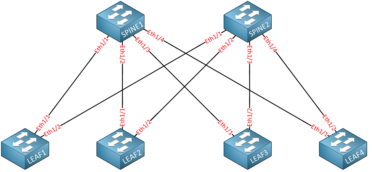
Let’s start with the physical topology:

We have two spine and four leaf switches. I’m using Cisco NX-OS 9000v version 10.4.5 on all switches. We should start by setting the correct MTU. The highest possible MTU can differ depending on your platform and OS version. On these Cisco NX-OS switches, the highest possible MTU value is 9216.
Let’s configure it on the spine switches:
SPINE1 & SPINE2
(config)# interface Ethernet 1/1-4
(config-if-range)# mtu 9216
And also on the leaf switches:
LEAF1-LEAF4
(config)# interface Ethernet 1/1-2
(config-if-range)# mtu 9216
Now, we can focus on IS-IS.
/31 Prefixes
On “normal” point-to-point links, you would use a /30 prefix. This means you’ll have:
- Network address
- Two usable IP addresses for hosts
- Broadcast address
A /31 prefix only has two IP addresses and can be used for point-to-point links. This will save you a lot of IP addresses. Let’s look at an example.
Let’s say we have 4 spine switches and 20 leaf switches. This means we’ll have 4 x 20 = 80 point-to-point links:
- 80 point-to-point links x 4 IP addresses ( /30 prefixes) = 320 IP addresses required for point-to-point links.
- 80 point-to-point links x 2 IP addresses ( /31 prefixes) = 160 IP addresses required for point-to-point links.
Our switches also require loopback interfaces. We’ll need 4 for the spine switches and 20 for the leaf switches. That’s 24 IP addresses for loopbacks.
In total, we would need:
- /30 prefixes: 344 IP addresses
- /31 prefixes: 184 IP addresses
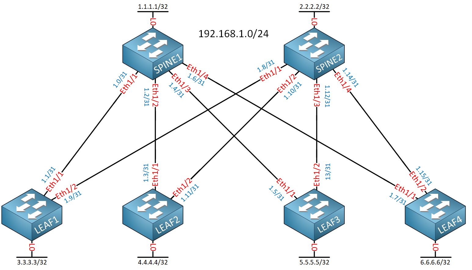
We’ll save quite some IP address space by using /31 prefixes. Here’s an example of what it could look like:

I took the 192.168.1.0/24 subnet and created many /31 prefixes for the physical interfaces. Let’s configure this on the switches.
Configurations
Want to take a look for yourself? Here, you will find the startup configuration of each device.
LEAF1
hostname LEAF1

interface Ethernet1/1
  no switchport
  mtu 9216
  mac-address 0050.c253.3001
  ip address 192.168.1.1/31
  no shutdown

interface Ethernet1/2
  no switchport
  mtu 9216
  mac-address 0050.c253.3002
  ip address 192.168.1.9/31
  no shutdown

interface loopback0
  ip address 3.3.3.3/32
LEAF2
hostname LEAF2

interface Ethernet1/1
  no switchport
  mtu 9216
  mac-address 0050.c253.4001
  ip address 192.168.1.3/31
  no shutdown

interface Ethernet1/2
  no switchport
  mtu 9216
  mac-address 0050.c253.4002
  ip address 192.168.1.11/31
  no shutdown

interface loopback0
  ip address 4.4.4.4/32
LEAF3
hostname LEAF3

interface Ethernet1/1
  no switchport
  mtu 9216
  mac-address 0050.c253.5001
  ip address 192.168.1.5/31
  no shutdown

interface Ethernet1/2
  no switchport
  mtu 9216
  mac-address 0050.c253.5002
  ip address 192.168.1.13/31
  no shutdown

interface loopback0
  ip address 5.5.5.5/32
LEAF4
hostname LEAF4

interface Ethernet1/1
  no switchport
  mtu 9216
  mac-address 0050.c253.6001
  ip address 192.168.1.7/31
  no shutdown

interface Ethernet1/2
  no switchport
  mtu 9216
  mac-address 0050.c253.6002
  ip address 192.168.1.15/31
  no shutdown

interface loopback0
  ip address 6.6.6.6/32
SPINE1
hostname SPINE1

interface Ethernet1/1
  no switchport
  mtu 9216
  mac-address 0050.c253.1001
  ip address 192.168.1.0/31
  no shutdown

interface Ethernet1/2
  no switchport
  mtu 9216
  mac-address 0050.c253.1002
  ip address 192.168.1.2/31
  no shutdown

interface Ethernet1/3
  no switchport
  mtu 9216
  mac-address 0050.c253.1003
  ip address 192.168.1.4/31
  no shutdown

interface Ethernet1/4
  no switchport
  mtu 9216
  mac-address 0050.c253.1004
  ip address 192.168.1.6/31
  no shutdown

interface loopback0
  ip address 1.1.1.1/32
SPINE2
hostname SPINE2

interface Ethernet1/1
  no switchport
  mtu 9216
  mac-address 0050.c253.2001
  ip address 192.168.1.8/31
  no shutdown

interface Ethernet1/2
  no switchport
  mtu 9216
  mac-address 0050.c253.2002
  ip address 192.168.1.10/31
  no shutdown

interface Ethernet1/3
  no switchport
  mtu 9216
  mac-address 0050.c253.2003
  ip address 192.168.1.12/31
  no shutdown

interface Ethernet1/4
  no switchport
  mtu 9216
  mac-address 0050.c253.2004
  ip address 192.168.1.14/31
  no shutdown

interface loopback0
ip address 2.2.2.2/32Now, let’s configure IS-IS. First, we need to enable the feature on all switches:
LEAF1-LEAF4, SPINE1 & SPINE2
(config)# feature isis
Let’s start a new IS-IS process and configure a unique network entity title (IS-IS-NET):
SPINE1(config)# router isis UNDERLAY
SPINE1(config-router)# net 49.0012.0000.0000.0001.00
SPINE2(config)# router isis UNDERLAY
SPINE2(config-router)# net 49.0012.0000.0000.0002.00LEAF1(config)# router isis UNDERLAY
LEAF1(config-router)# net 49.0012.0000.0000.0003.00LEAF2(config)# router isis UNDERLAY
LEAF2(config-router)# net 49.0012.0000.0000.0004.00LEAF3(config)# router isis UNDERLAY
LEAF3(config-router)# net 49.0012.0000.0000.0005.00LEAF4(config)# router isis UNDERLAY
LEAF4(config-router)# net 49.0012.0000.0000.0006.00We’ll call the process “UNDERLAY”.
By default, IS-IS will establish level 1 and level 2 neighbor adjacencies. I’ll change it so it only creates level 2 neighbor adjacencies and I’ll also enable logging of adjacency changes:
LEAF1-LEAF4, SPINE1 & SPINE2
(config)# router isis UNDERLAY
(config-router)# is-type level-2
(config-router)# log-adjacency-changes
That’s it.
Let’s enable IS-IS on the loopback interfaces:
LEAF1-LEAF4, SPINE1 & SPINE2
(config)# interface Loopback 0
(config-if)# ip router isis UNDERLAY
Let’s configure IS-IS on the Ethernet interfaces. Make sure you set the network type to point-to-point so we don’t have a DIS election. We’ll start with the leaf switches:
LEAF1-LEAF4
(config)# interface Ethernet 1/1-2
(config-if-range)# isis network point-to-point
(config-if-range)# ip router isis UNDERLAY
And here are the spine switches:
SPINE1 & SPINE2
(config)# interface Ethernet 1/1-4
(config-if-range)# isis network point-to-point
(config-if-range)# ip router isis UNDERLAY
That completes the configuration.
Verification
Let’s look at the IS-IS process in general:
SPINE1# show isis

ISIS process : UNDERLAY
 Instance number :  1
 UUID: 1090519320
 Process ID 19208
VRF: default
  System ID : 0000.0000.0001  IS-Type : L2
  SAP : 412  Queue Handle : 12
  Maximum LSP MTU: 1492
  Stateful HA enabled
  Graceful Restart enabled. State: Inactive
  Last graceful restart status : none
  Start-Mode Complete
  BFD IPv4 is globally disabled for ISIS process: UNDERLAY
  BFD IPv6 is globally disabled for ISIS process: UNDERLAY
  Topology-mode is base
  Metric-style : advertise(wide), accept(narrow, wide)
  Area address(es) :
    49.0012
  Process is up and running
  VRF ID: 1
  Stale routes during non-graceful controlled restart
  Enable resolution of L3->L2 address for ISIS adjacency
  SRTE: Not registered
  OAM: Not registered
  SR IPv4 is not configured and disabled for ISIS process: UNDERLAY
  SR IPv6 is not configured and disabled for ISIS process: UNDERLAY
 SRv6 is disabled for ISIS process: UNDERLAY
  Interfaces supported by IS-IS :
    loopback0
    Ethernet1/1
    Ethernet1/2
    Ethernet1/3
    Ethernet1/4
  Topology : 0
  Address family IPv4 unicast :
    Number of interface : 5
    Distance : 115
    Default-information not originated
  Address family IPv6 unicast :
    Number of interface : 0
    Distance : 115
    Default-information not originated
  Topology : 2
  Address family IPv4 unicast :
    Number of interface : 0
    Distance : 115
    Default-information not originated
  Address family IPv6 unicast :
    Number of interface : 0
    Distance : 115
    Default-information not originated
  Level1
  No auth type and keychain
  Auth check set
  Level2
  No auth type and keychain
  Auth check set
  L1 Next SPF: Inactive
  L2 Next SPF: Inactive
  Attached bits
   MT-0 L-1: Att 0 Spf-att 0 Cfg 1 Adv-att 0
   MT-0 L-2: Att 0 Spf-att 0 Cfg 1 Adv-att 0
Above, you see some general information such as the process name, the level, and the interfaces we use. You can also see some information per interface:
SPINE1# show isis interface Ethernet 1/1
IS-IS process: UNDERLAY VRF: default
Ethernet1/1, Interface status: protocol-up/link-up/admin-up
  IP address: 192.168.1.0, IP subnet: 192.168.1.0/31
  IPv6 routing is disabled
    No auth type and keychain
    Auth check set
  Index: 0x0002, Local Circuit ID: 0x01, Circuit Type: L2
  Prefix suppress is disabled globally on interface Ethernet1/1
  Level 1
    Address-family IPv4 Advertise Passive only is disabled
    Address-family IPv6 Advertise Passive only is disabled
  Level 2
    Address-family IPv4 Advertise Passive only is disabled
    Address-family IPv6 Advertise Passive only is disabled
  BFD IPv4 is locally disabled for Interface Ethernet1/1
  BFD IPv6 is locally disabled for Interface Ethernet1/1
  MTR is disabled
  Extended Local Circuit ID: 0x1A000000, P2P Circuit ID: 0000.0000.0000.00
  Retx interval: 5, Retx throttle interval: 66 ms
  LSP interval: 33 ms, MTU: 9216
  MTU check OFF on P2P interface
  P2P Adjs: 1, AdjsUp: 1, Priority 64
  Hello Interval: 10, Multi: 3, Next IIH: 00:00:01
  MT    Adjs   AdjsUp  Metric   CSNP  Next CSNP  Last LSP ID
  1          0        0      40     60  Inactive   ffff.ffff.ffff.ff-ff
  2          1        1      40     60  00:01:00   ffff.ffff.ffff.ff-ff
  Topologies enabled:
    L  MT  Metric  MetricCfg  Fwdng IPV4-MT  IPV4Cfg  IPV6-MT  IPV6Cfg
    1  0        40      no   DN    DN       no       DN       no
    2  0        40      no   UP    UP       yes      DN       no
The output above is helpful because it shows we have a point-to-point adjacency. Let’s check our neighbor adjacencies:
SPINE1# show isis adjacency
IS-IS process: UNDERLAY VRF: default
IS-IS adjacency database:
Legend: '!': No AF level connectivity in given topology
System ID       SNPA            Level  State  Hold Time  Interface
LEAF1           N/A             2      UP     00:00:31   Ethernet1/1
LEAF2           N/A             2      UP     00:00:22   Ethernet1/2
LEAF3           N/A             2      UP     00:00:30   Ethernet1/3
LEAF4           N/A             2      UP     00:00:32   Ethernet1/4
SPINE2# show isis adjacency
IS-IS process: UNDERLAY VRF: default
IS-IS adjacency database:
Legend: '!': No AF level connectivity in given topology
System ID SNPA Level State Hold Time Interface
LEAF1 N/A 2 UP 00:00:27 Ethernet1/1
LEAF2 N/A 2 UP 00:00:29 Ethernet1/2
LEAF3 N/A 2 UP 00:00:27 Ethernet1/3
LEAF4 N/A 2 UP 00:00:25 Ethernet1/4Each spine switch has four neighbor adjacencies, one with each leaf switch. Let’s check some routes:
SPINE1# show ip route isis
IP Route Table for VRF "default"
'*' denotes best ucast next-hop
'**' denotes best mcast next-hop
'[x/y]' denotes [preference/metric]
'%' in via output denotes VRF

2.2.2.2/32, ubest/mbest: 4/0
    *via 192.168.1.1, Eth1/1, [115/81], 00:04:04, isis-UNDERLAY, L2
    *via 192.168.1.3, Eth1/2, [115/81], 00:04:16, isis-UNDERLAY, L2
    *via 192.168.1.5, Eth1/3, [115/81], 00:04:19, isis-UNDERLAY, L2
    *via 192.168.1.7, Eth1/4, [115/81], 00:04:16, isis-UNDERLAY, L2
3.3.3.3/32, ubest/mbest: 1/0
    *via 192.168.1.1, Eth1/1, [115/41], 00:04:04, isis-UNDERLAY, L2
4.4.4.4/32, ubest/mbest: 1/0
    *via 192.168.1.3, Eth1/2, [115/41], 00:04:21, isis-UNDERLAY, L2
5.5.5.5/32, ubest/mbest: 1/0
    *via 192.168.1.5, Eth1/3, [115/41], 00:04:21, isis-UNDERLAY, L2
6.6.6.6/32, ubest/mbest: 1/0
    *via 192.168.1.7, Eth1/4, [115/41], 00:04:19, isis-UNDERLAY, L2
192.168.1.8/31, ubest/mbest: 1/0
    *via 192.168.1.1, Eth1/1, [115/80], 00:04:04, isis-UNDERLAY, L2
192.168.1.10/31, ubest/mbest: 1/0
    *via 192.168.1.3, Eth1/2, [115/80], 00:04:21, isis-UNDERLAY, L2
192.168.1.12/31, ubest/mbest: 1/0
    *via 192.168.1.5, Eth1/3, [115/80], 00:04:21, isis-UNDERLAY, L2
192.168.1.14/31, ubest/mbest: 1/0
    *via 192.168.1.7, Eth1/4, [115/80], 00:04:19, isis-UNDERLAY, L2
SPINE2# show ip route isis
IP Route Table for VRF "default"
'*' denotes best ucast next-hop
'**' denotes best mcast next-hop
'[x/y]' denotes [preference/metric]
'%' in via output denotes VRF
1.1.1.1/32, ubest/mbest: 4/0
*via 192.168.1.9, Eth1/1, [115/81], 00:04:37, isis-UNDERLAY, L2
*via 192.168.1.11, Eth1/2, [115/81], 00:04:47, isis-UNDERLAY, L2
*via 192.168.1.13, Eth1/3, [115/81], 00:04:47, isis-UNDERLAY, L2
*via 192.168.1.15, Eth1/4, [115/81], 00:04:47, isis-UNDERLAY, L2
3.3.3.3/32, ubest/mbest: 1/0
*via 192.168.1.9, Eth1/1, [115/41], 00:04:37, isis-UNDERLAY, L2
4.4.4.4/32, ubest/mbest: 1/0
*via 192.168.1.11, Eth1/2, [115/41], 00:04:48, isis-UNDERLAY, L2
5.5.5.5/32, ubest/mbest: 1/0
*via 192.168.1.13, Eth1/3, [115/41], 00:04:48, isis-UNDERLAY, L2
6.6.6.6/32, ubest/mbest: 1/0
*via 192.168.1.15, Eth1/4, [115/41], 00:04:47, isis-UNDERLAY, L2
192.168.1.0/31, ubest/mbest: 1/0
*via 192.168.1.9, Eth1/1, [115/80], 00:04:37, isis-UNDERLAY, L2
192.168.1.2/31, ubest/mbest: 1/0
*via 192.168.1.11, Eth1/2, [115/80], 00:04:48, isis-UNDERLAY, L2
192.168.1.4/31, ubest/mbest: 1/0
*via 192.168.1.13, Eth1/3, [115/80], 00:04:48, isis-UNDERLAY, L2
192.168.1.6/31, ubest/mbest: 1/0
*via 192.168.1.15, Eth1/4, [115/80], 00:04:47, isis-UNDERLAY, L2This shows us everything we need. We see all IP addresses on the loopback interfaces advertised by IS-IS. Here’s one of the leaf switches:
LEAF1# show ip route isis
IP Route Table for VRF "default"
'*' denotes best ucast next-hop
'**' denotes best mcast next-hop
'[x/y]' denotes [preference/metric]
'%' in via output denotes VRF

1.1.1.1/32, ubest/mbest: 1/0
    *via 192.168.1.0, Eth1/1, [115/41], 00:05:08, isis-UNDERLAY, L2
2.2.2.2/32, ubest/mbest: 1/0
    *via 192.168.1.8, Eth1/2, [115/41], 00:05:07, isis-UNDERLAY, L2
4.4.4.4/32, ubest/mbest: 2/0
    *via 192.168.1.0, Eth1/1, [115/81], 00:05:07, isis-UNDERLAY, L2
    *via 192.168.1.8, Eth1/2, [115/81], 00:05:07, isis-UNDERLAY, L2
5.5.5.5/32, ubest/mbest: 2/0
    *via 192.168.1.0, Eth1/1, [115/81], 00:05:07, isis-UNDERLAY, L2
    *via 192.168.1.8, Eth1/2, [115/81], 00:05:07, isis-UNDERLAY, L2
6.6.6.6/32, ubest/mbest: 2/0
    *via 192.168.1.0, Eth1/1, [115/81], 00:05:07, isis-UNDERLAY, L2
    *via 192.168.1.8, Eth1/2, [115/81], 00:05:07, isis-UNDERLAY, L2
192.168.1.2/31, ubest/mbest: 1/0
    *via 192.168.1.0, Eth1/1, [115/80], 00:05:08, isis-UNDERLAY, L2
192.168.1.4/31, ubest/mbest: 1/0
    *via 192.168.1.0, Eth1/1, [115/80], 00:05:08, isis-UNDERLAY, L2
192.168.1.6/31, ubest/mbest: 1/0
    *via 192.168.1.0, Eth1/1, [115/80], 00:05:08, isis-UNDERLAY, L2
192.168.1.10/31, ubest/mbest: 1/0
    *via 192.168.1.8, Eth1/2, [115/80], 00:05:07, isis-UNDERLAY, L2
192.168.1.12/31, ubest/mbest: 1/0
    *via 192.168.1.8, Eth1/2, [115/80], 00:05:07, isis-UNDERLAY, L2
192.168.1.14/31, ubest/mbest: 1/0
    *via 192.168.1.8, Eth1/2, [115/80], 00:05:07, isis-UNDERLAY, L2
LEAF1 knows how to reach the different loopback interfaces of the other leaf switches. The other leaf switches would show a similar output. This is everything we need to configure an overlay.
Configurations
Want to take a look for yourself? Here, you will find the final configuration of each device.
LEAF1
hostname LEAF1

feature isis

interface Ethernet1/1
  no switchport
  mtu 9216
  mac-address 0050.c253.3001
  ip address 192.168.1.1/31
  isis network point-to-point
  ip router isis UNDERLAY
  no shutdown

interface Ethernet1/2
  no switchport
  mtu 9216
  mac-address 0050.c253.3002
  ip address 192.168.1.9/31
  isis network point-to-point
  ip router isis UNDERLAY
  no shutdown

interface Ethernet1/3
  switchport access vlan 10

interface loopback0
  ip address 3.3.3.3/32
  ip router isis UNDERLAY

router isis UNDERLAY
  net 49.0012.0000.0000.0003.00
  is-type level-2
  log-adjacency-changes
LEAF2
hostname LEAF2

feature isis

interface Ethernet1/1
  no switchport
  mtu 9216
  mac-address 0050.c253.4001
  ip address 192.168.1.3/31
  isis network point-to-point
  ip router isis UNDERLAY
  no shutdown

interface Ethernet1/2
  no switchport
  mtu 9216
  mac-address 0050.c253.4002
  ip address 192.168.1.11/31
  isis network point-to-point
  ip router isis UNDERLAY
  no shutdown

interface Ethernet1/3
  switchport access vlan 10

interface loopback0
  ip address 4.4.4.4/32
  ip router isis UNDERLAY

router isis UNDERLAY
  net 49.0012.0000.0000.0004.00
  is-type level-2
  log-adjacency-changes
LEAF3
hostname LEAF3

feature isis

interface Ethernet1/1
  no switchport
  mtu 9216
  mac-address 0050.c253.5001
  ip address 192.168.1.5/31
  isis network point-to-point
  ip router isis UNDERLAY
  no shutdown

interface Ethernet1/2
  no switchport
  mtu 9216
  mac-address 0050.c253.5002
  ip address 192.168.1.13/31
  isis network point-to-point
  ip router isis UNDERLAY
  no shutdown

interface Ethernet1/3
  switchport access vlan 10

interface loopback0
  ip address 5.5.5.5/32
  ip router isis UNDERLAY

router isis UNDERLAY
  net 49.0012.0000.0000.0005.00
  is-type level-2
  log-adjacency-changes
LEAF4
hostname LEAF4

feature isis

interface Ethernet1/1
  no switchport
  mtu 9216
  mac-address 0050.c253.6001
  ip address 192.168.1.7/31
  isis network point-to-point
  ip router isis UNDERLAY
  no shutdown

interface Ethernet1/2
  no switchport
  mtu 9216
  mac-address 0050.c253.6002
  ip address 192.168.1.15/31
  isis network point-to-point
  ip router isis UNDERLAY
  no shutdown

interface Ethernet1/3
  switchport access vlan 10

interface loopback0
  ip address 6.6.6.6/32
  ip router isis UNDERLAY

router isis UNDERLAY
  net 49.0012.0000.0000.0006.00
  is-type level-2
  log-adjacency-changes
SPINE1
hostname SPINE1

feature isis

interface Ethernet1/1
  no switchport
  mtu 9216
  mac-address 0050.c253.1001
  ip address 192.168.1.0/31
  isis network point-to-point
  ip router isis UNDERLAY
  no shutdown

interface Ethernet1/2
  no switchport
  mtu 9216
  mac-address 0050.c253.1002
  ip address 192.168.1.2/31
  isis network point-to-point
  ip router isis UNDERLAY
  no shutdown

interface Ethernet1/3
  no switchport
  mtu 9216
  mac-address 0050.c253.1003
  ip address 192.168.1.4/31
  isis network point-to-point
  ip router isis UNDERLAY
  no shutdown

interface Ethernet1/4
  no switchport
  mtu 9216
  mac-address 0050.c253.1004
  ip address 192.168.1.6/31
  isis network point-to-point
  ip router isis UNDERLAY
  no shutdown

interface loopback0
  ip address 1.1.1.1/32
  ip router isis UNDERLAY

router isis UNDERLAY
  net 49.0012.0000.0000.0001.00
  is-type level-2
  log-adjacency-changes
SPINE2
hostname SPINE2

feature isis

interface Ethernet1/1
  no switchport
  mtu 9216
  mac-address 0050.c253.2001
  ip address 192.168.1.8/31
  isis network point-to-point
  ip router isis UNDERLAY
  no shutdown

interface Ethernet1/2
  no switchport
  mtu 9216
  mac-address 0050.c253.2002
  ip address 192.168.1.10/31
  isis network point-to-point
  ip router isis UNDERLAY
  no shutdown

interface Ethernet1/3
  no switchport
  mtu 9216
  mac-address 0050.c253.2003
  ip address 192.168.1.12/31
  isis network point-to-point
  ip router isis UNDERLAY
  no shutdown

interface Ethernet1/4
  no switchport
  mtu 9216
  mac-address 0050.c253.2004
  ip address 192.168.1.14/31
  isis network point-to-point
  ip router isis UNDERLAY
  no shutdown

interface loopback0
  ip address 2.2.2.2/32
  ip router isis UNDERLAY

router isis UNDERLAY
  net 49.0012.0000.0000.0002.00
  is-type level-2
  log-adjacency-changes
Unnumbered Interfaces
Time for our second example. We’ll use IP unnumbered and borrow the IP addresses from the loopback interfaces. This saves a lot of IP addresses and the routing tables will only show what we need: The IP addresses on the loopback interfaces. If you would have 4 spine switches and 20 leaf switches, you would only need 24 IP addresses. One for the loopback interface of each device.
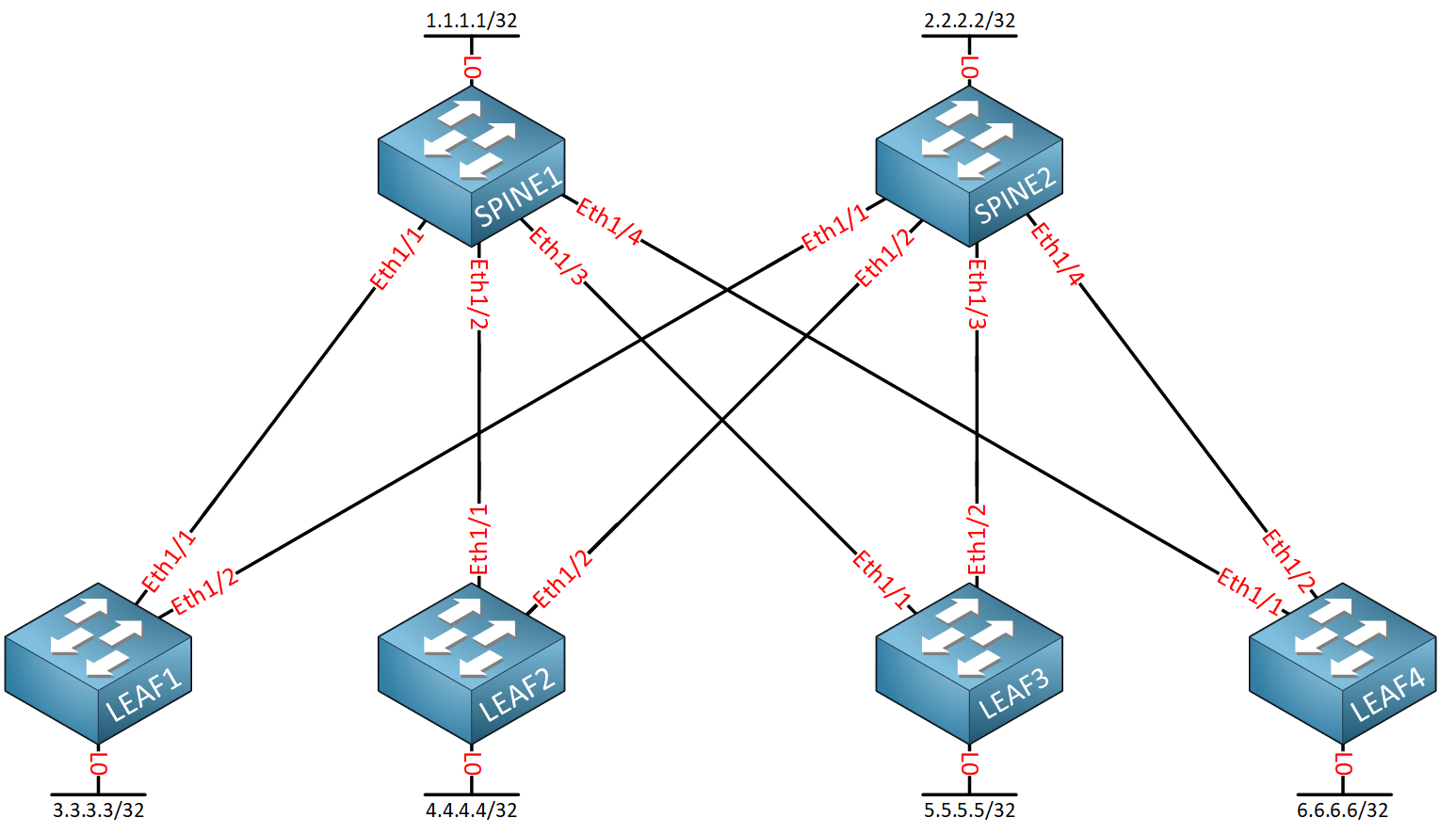
Let’s see how to configure this. Here is the topology:

We use the same topology as before, but this time, we only have IP addresses configured on the loopback interfaces.
Configurations
Want to take a look for yourself? Here, you will find the startup configuration of each device.
LEAF1
hostname LEAF1

interface Ethernet1/1
  no switchport
  mtu 9216
  mac-address 0050.c253.3001
  no shutdown

interface Ethernet1/2
  no switchport
  mtu 9216
  mac-address 0050.c253.3002
  no shutdown

interface loopback0
  ip address 3.3.3.3/32
LEAF2
hostname LEAF2

interface Ethernet1/1
  no switchport
  mtu 9216
  mac-address 0050.c253.4001
  no shutdown

interface Ethernet1/2
  no switchport
  mtu 9216
  mac-address 0050.c253.4002
  no shutdown

interface loopback0
  ip address 4.4.4.4/32
LEAF3
hostname LEAF3

interface Ethernet1/1
  no switchport
  mtu 9216
  mac-address 0050.c253.5001
  no shutdown

interface Ethernet1/2
  no switchport
  mtu 9216
  mac-address 0050.c253.5002
  no shutdown

interface loopback0
  ip address 5.5.5.5/32
LEAF4
hostname LEAF4

interface Ethernet1/1
  no switchport
  mtu 9216
  mac-address 0050.c253.6001
  no shutdown

interface Ethernet1/2
  no switchport
  mtu 9216
  mac-address 0050.c253.6002
  no shutdown

interface loopback0
  ip address 6.6.6.6/32
SPINE1
hostname SPINE1

interface Ethernet1/1
  no switchport
  mtu 9216
  mac-address 0050.c253.1001
  no shutdown

interface Ethernet1/2
  no switchport
  mtu 9216
  mac-address 0050.c253.1002
  no shutdown

interface Ethernet1/3
  no switchport
  mtu 9216
  mac-address 0050.c253.1003
  no shutdown

interface Ethernet1/4
  no switchport
  mtu 9216
  mac-address 0050.c253.1004
  no shutdown

interface loopback0
  ip address 1.1.1.1/32
SPINE2
hostname SPINE2

interface Ethernet1/1
  no switchport
  mtu 9216
  mac-address 0050.c253.2001
  no shutdown

interface Ethernet1/2
  no switchport
  mtu 9216
  mac-address 0050.c253.2002
  no shutdown

interface Ethernet1/3
  no switchport
  mtu 9216
  mac-address 0050.c253.2003
  no shutdown

interface Ethernet1/4
  no switchport
  mtu 9216
  mac-address 0050.c253.2004
  no shutdown

interface loopback0
  ip address 2.2.2.2/32
Let’s configure IS-IS. We’ll enable the feature first:


