Lesson Contents
This is the first VXLAN lesson, and we’ll work with the Cisco Nexus (NX-OS) 9000v switches.
In this lesson, we’ll use static ingress replication, which means manually configuring the remote VXLAN Tunnel Endpoint (VTEP)s on each VTEP. Each VTEP replicates incoming broadcast, unknown-unicast, and multicast (BUM) traffic to all configured VTEPs. It’s the most simple method to configure VXLAN, because you don’t have to configure multicast or BGP EVPN. It uses a flood and learn mechanism on the data plane.
Static ingress replication is suitable for smaller networks. It’s easy to configure, and you don’t have a complex control plane like when you use VXLAN with multicast or MP-BGP EVPN. You also have greater control because you manually configure all VTEPs.
The biggest issues with static ingress replication are related to scalability. You need to manually configure all VTEPs so there is administrative overhead. When you remove a VTEP, it has to be configured on all VTEPs. Also, BUM traffic is replicated to all other VTEPs.
This is a great way to get started with VXLAN and familiarize yourself with the different configurations and show commands. We’ll add more complexity throughout the series of VXLAN lessons.
Configuration
Let’s get started. This is the topology we’ll use:
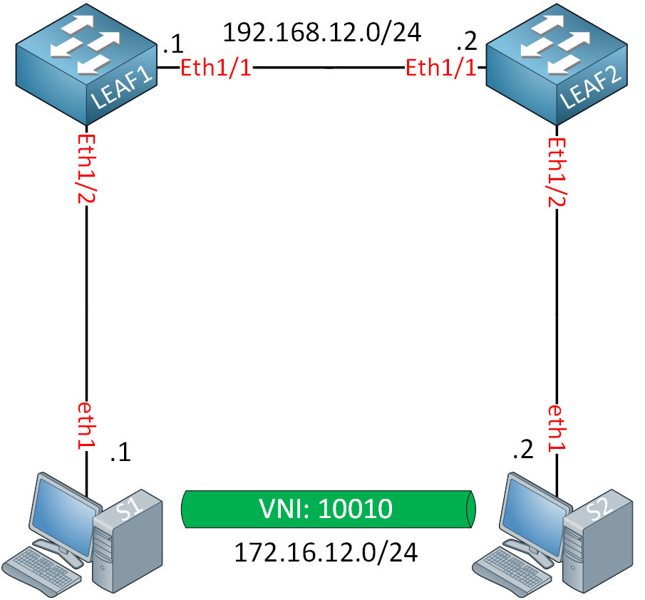
We have two switches connected to each other with a L3 link. Our two servers are connected to L2 interfaces and use IP addresses in the same subnet. They won’t be able to communicate with each other until we configure VXLAN.
For this topology, I’m using two device types:
- Leaf switches: Cisco Nexus 9000v switches running nxos64-cs.10.2.7.M.bin.
- Hosts: Ubuntu docker containers.
Usually, I like to use routers as hosts, but for these VXLAN labs, I decided to use Ubuntu containers. These hosts only need to send some ICMP traffic between each other, and each Ubuntu container only requires a couple of MB of RAM.
Cisco Nexus 9000v switches require 8 GB of RAM each. This is a small topology, but with two spine switches, four leaf switches, and many hosts, the memory requirements add up quickly. This lab requires about ~17GB of RAM to virtualize.
Having said that, let’s start with the configuration.
Underlay Network
First, we have to set up the underlay network. Each leaf switch requires a loopback interface with an IP address that we’ll use for the VTEP addresses. We’ll have to configure some IP addresses, and we’ll need an IGP to advertise the loopback interfaces.
Leaf Switches
We’ll start with the interfaces:
LEAF1(config)# interface Ethernet 1/1
LEAF1(config-if)# no switchport
LEAF1(config-if)# mac-address 0050.c253.1001
LEAF1(config-if)# ip address 192.168.12.1/24

LEAF1(config)# interface Loopback 0
LEAF1(config-if)# ip address 1.1.1.1/32
LEAF2(config)# interface Ethernet 1/1
LEAF2(config-if)# no switchport
LEAF2(config-if)# mac-address 0050.c253.2001
LEAF2(config-if)# ip address 192.168.12.2/24
LEAF2(config)# interface Loopback 0
LEAF2(config-if)# ip address 2.2.2.2/32I’m using static MAC addresses so that it’s easier to recognize our devices in a packet capture. It also makes it easier to lab this in the future because otherwise, the switches could use random MAC addresses each time we boot the topology.
VTEPs need loopback interfaces, so we need an IGP to advertise them. I’ll keep it simple, so we’ll use OSPF:
LEAF1 & LEAF2
(config)# feature ospf

(config)# router ospf 1

(config)# interface Ethernet 1/1
(config-if)# ip ospf network point-to-point
(config-if)# ip router ospf 1 area 0.0.0.0

(config)# interface Loopback 0
(config-if)# ip router ospf 1 area 0.0.0.0
That’s all we need.
Hosts
I’ll also configure a static MAC address and IP address on our hosts:
root@S1:/# ip link set dev eth1 address 00:50:c2:53:30:01
root@S1:/# ip addr add 172.16.12.1/24 dev eth1
root@S2:/# ip link set dev eth1 address 00:50:c2:53:40:01
root@S2:/# ip addr add 172.16.12.2/24 dev eth1This completes the configuration of the underlay network.
Overlay
For the overlay network, we need to configure the following:
- VXLAN Network Identifier (VNI)
- Network Virtual Interface (NVE)
Let me walk you through this.
VNI
We must configure our VNI and map a VLAN to a new VNI. Before we can do this, we have to enable the VN-Segment feature:
LEAF1#(config)# feature vn-segment-vlan-basedNow, we can use the vn-segment command:
LEAF1(config)# vlan 10
LEAF1(config-vlan)# vn-segment 10010
This assigns VLAN 10 to VNI 10010. You can pick whatever values you like. The interfaces on the leaf switches that connect to the hosts are normal access interfaces and are assigned to VLAN 10:
LEAF1(config)# interface Ethernet 1/2
LEAF1(config-if)# switchport access vlan 10
We’ll configure the same thing on LEAF2:
LEAF2#(config)# feature vn-segment-vlan-based
LEAF2(config)# vlan 10
LEAF2(config-vlan)# vn-segment 10010
LEAF2(config)# interface Ethernet 1/2
LEAF2(config-if)# switchport access vlan 10
That’s all we need to configure for the VNI.
NVE Interface
Before we can create the NVE interface, we need to enable the NV overlay feature:
LEAF1(config)# feature nv overlayNow, we can create an NVE interface:
LEAF1(config)# interface nve 1
LEAF1(config-if-nve)# no shutdown
LEAF1(config-if-nve)# source-interface Loopback 0
LEAF1(config-if-nve)# member vni 10010
LEAF1(config-if-nve-vni)# ingress-replication protocol static
LEAF1(config-if-nve-vni-ingr-rep)# peer-ip 2.2.2.2
The NVE interface uses the loopback 0 interface as the source. We configure VNI 10010 to use static ingress replication, and 2.2.2.2 (LEAF2) is a peer.
We’ll configure the same thing on LEAF2:
LEAF2(config)# feature nv overlay

LEAF2(config)# interface nve 1
LEAF2(config-if-nve)# no shutdown
LEAF2(config-if-nve)# source-interface Loopback 0
LEAF2(config-if-nve)# member vni 10010
LEAF2(config-if-nve-vni)# ingress-replication protocol static
LEAF2(config-if-nve-vni-ingr-rep)# peer-ip 1.1.1.1
This completes our overlay network configuration.
Verification
Everything is in place. Let’s verify our work.
Underlay Network
Let’s make sure the underlay network is working. We have an OSPF neighbor adjacency:
LEAF1# show ip ospf neighbors
 OSPF Process ID 1 VRF default
 Total number of neighbors: 1
 Neighbor ID     Pri State            Up Time  Address         Interface
 2.2.2.2           1 FULL/ -          00:00:05 192.168.12.2    Eth1/1
And we can ping between the two loopback interfaces:
LEAF1# ping 2.2.2.2 source 1.1.1.1
PING 2.2.2.2 (2.2.2.2) from 1.1.1.1: 56 data bytes
64 bytes from 2.2.2.2: icmp_seq=0 ttl=254 time=2.319 ms
64 bytes from 2.2.2.2: icmp_seq=1 ttl=254 time=1.456 ms
64 bytes from 2.2.2.2: icmp_seq=2 ttl=254 time=1.312 ms
64 bytes from 2.2.2.2: icmp_seq=3 ttl=254 time=1.481 ms
64 bytes from 2.2.2.2: icmp_seq=4 ttl=254 time=1.373 ms
That’s all we need to know.
Overlay Network
For the overlay network, there are a couple of things to check. First of all, let’s check the VLAN to VNI mapping:
LEAF1# show vxlan
Vlan            VN-Segment
====            ==========
10              10010
Our VLAN is mapped to a VNI. The other thing to check is the NVE interface. There are a couple of show commands that give similar outputs. Let’s check if our two switches see each other as peers:
LEAF1# show nve peers
Interface Peer-IP                                 State LearnType Uptime   Router-Mac
--------- --------------------------------------  ----- --------- -------- -----------------
nve1      2.2.2.2                                 Up    DP        00:10:12 n/a
The state is “up” so this is looking good. The learn type shows “DP,” which means data plane. This means we use data plane learning (instead of the control plane). We can take a closer look with the detail parameter:
LEAF1# show nve peers detail
Details of nve Peers:
----------------------------------------
Peer-Ip: 2.2.2.2
    NVE Interface       : nve1
    Peer State          : Up
    Peer Uptime         : 00:10:33
    Router-Mac          : n/a
    Peer First VNI      : 10010
    Time since Create   : 00:10:33
    Configured VNIs     : 10010
    Provision State     : peer-add-complete
    Learnt CP VNIs      : 10010
    vni assignment mode : SYMMETRIC
    Peer Location       : N/A
This output also shows the uptime, first VNI, etc. Here’s one more command that gives a similar output:
LEAF1# show nve vni
Codes: CP - Control Plane        DP - Data Plane
       UC - Unconfigured         SA - Suppress ARP
       SU - Suppress Unknown Unicast
       Xconn - Crossconnect
       MS-IR - Multisite Ingress Replication
       HYB - Hybrid IRB mode

Interface VNI      Multicast-group   State Mode Type [BD/VRF]      Flags
--------- -------- ----------------- ----- ---- ------------------ -----
nve1      10010    UnicastStatic     Up    DP   L2 [10]
This tells us that the NVE1 interface uses static ingress replication for VNI 10010, that the state is up, and that we use data plane learning.
We can also check the NVE interface:
LEAF1# show interface nve 1
nve1 is up
admin state is up,  Hardware: NVE
  MTU 9216 bytes
  Encapsulation VXLAN
  Auto-mdix is turned off
  RX
    ucast: 0 pkts, 0 bytes - mcast: 0 pkts, 0 bytes
  TX
    ucast: 1 pkts, 120 bytes - mcast: 0 pkts, 0 bytes
The NVE interface is up, and the encapsulation is VXLAN. You can also see the number of packets sent and received. Here is a similar command:
LEAF1# show nve interface
Interface: nve1, State: Up, encapsulation: VXLAN
 VPC Capability: VPC-VIP-Only [not-notified]
 Local Router MAC: 0cc6.9700.1b08
 Host Learning Mode: Data-Plane
 Source-Interface: loopback0 (primary: 1.1.1.1, secondary: 0.0.0.0)
This gives us a bit more information. You can see even more if you add the detail parameter:
LEAF1# show nve interface nve 1 detail
Interface: nve1, State: Up, encapsulation: VXLAN
 VPC Capability: VPC-VIP-Only [not-notified]
 Local Router MAC: 0cc6.9700.1b08
 Host Learning Mode: Data-Plane
 Source-Interface: loopback0 (primary: 1.1.1.1, secondary: 0.0.0.0)
 Source Interface State: Up
 Virtual RMAC Advertisement: No
 NVE Flags:
 Interface Handle: 0x49000001
 Source Interface hold-down-time: 180
 Source Interface hold-up-time: 30
 Remaining hold-down time: 0 seconds
 Virtual Router MAC: N/A
 Interface state: nve-intf-add-complete
 Fabric convergence time: 135 seconds
 Fabric convergence time left: 0 seconds
Last but not least, let’s check the MAC address table of one of the leaf switches:
LEAF1(config)# show mac address-table dynamic
Legend:
        * - primary entry, G - Gateway MAC, (R) - Routed MAC, O - Overlay MAC
        age - seconds since last seen,+ - primary entry using vPC Peer-Link,
        (T) - True, (F) - False, C - ControlPlane MAC, ~ - vsan,
        (NA)- Not Applicable
   VLAN     MAC Address      Type      age     Secure NTFY Ports
---------+-----------------+--------+---------+------+----+------------------
It’s currently empty because our hosts haven’t sent anything yet. Let’s send a ping from S1 to S2:
root@S1:/# ping 172.16.12.2 -c 5
PING 172.16.12.2 (172.16.12.2) 56(84) bytes of data.
64 bytes from 172.16.12.2: icmp_seq=1 ttl=64 time=6.51 ms
64 bytes from 172.16.12.2: icmp_seq=2 ttl=64 time=3.49 ms
64 bytes from 172.16.12.2: icmp_seq=3 ttl=64 time=4.94 ms
64 bytes from 172.16.12.2: icmp_seq=4 ttl=64 time=4.08 ms
64 bytes from 172.16.12.2: icmp_seq=5 ttl=64 time=3.41 ms

--- 172.16.12.2 ping statistics ---
5 packets transmitted, 5 received, 0% packet loss, time 4005ms
rtt min/avg/max/mdev = 3.414/4.486/6.506/1.148 ms
Our ping works. That tells us that VXLAN encapsulation works because these two hosts are in the same subnet, and we have an L3 link between the leaf switches.
Packet Capture
If you want to see VXLAN packets in action, we’ll have to capture some traffic. Let’s look at a Wireshark capture of this traffic. The first frame is an ARP:
Frame 7: 110 bytes on wire (880 bits), 110 bytes captured (880 bits) on interface eth1, id 0
Ethernet II, Src: NVE_53:10:01 (00:50:c2:53:10:01), Dst: NVE_53:20:01 (00:50:c2:53:20:01)
    Destination: NVE_53:20:01 (00:50:c2:53:20:01)
    Source: NVE_53:10:01 (00:50:c2:53:10:01)
    Type: IPv4 (0x0800)
Internet Protocol Version 4, Src: 1.1.1.1, Dst: 2.2.2.2
User Datagram Protocol, Src Port: 64901, Dst Port: 4789
Virtual eXtensible Local Area Network
    Flags: 0x0800, VXLAN Network ID (VNI)
        0... .... .... .... = GBP Extension: Not defined
        .... 1... .... .... = VXLAN Network ID (VNI): True
        .... .... .0.. .... = Don't Learn: False
        .... .... .... 0... = Policy Applied: False
        .000 .000 0.00 .000 = Reserved(R): 0x0000
    Group Policy ID: 0
    VXLAN Network Identifier (VNI): 10010
    Reserved: 0
Ethernet II, Src: NVE_53:30:01 (00:50:c2:53:30:01), Dst: Broadcast (ff:ff:ff:ff:ff:ff)
    Destination: Broadcast (ff:ff:ff:ff:ff:ff)
    Source: NVE_53:30:01 (00:50:c2:53:30:01)
    Type: ARP (0x0806)
    Trailer: 000000000000000000000000000000000000
Address Resolution Protocol (request)
    Hardware type: Ethernet (1)
    Protocol type: IPv4 (0x0800)
    Hardware size: 6
    Protocol size: 4
    Opcode: request (1)
    Sender MAC address: NVE_53:30:01 (00:50:c2:53:30:01)
    Sender IP address: 172.16.12.1
    Target MAC address: Xerox_00:00:00 (00:00:00:00:00:00)
    Target IP address: 172.16.12.2
Above, you see a VXLAN encapsulated packet. Let me explain:
- We have an IP packet from LEAF1 (1.1.1.1) to LEAF2 (2.2.2.2).
- The UDP source port is random. This is helpful when you use ECMP because it allows you to do load balancing.
- The UDP destination port is 4789 for VXLAN.
- The VNI is 10010.
- The inner packet is an ARP request from S1 (00:50:c2:53:30:01) with destination broadcast.
This is an example of BUM traffic, which is replicated and sent to all configured VTEPs.
Here is the ARP reply from S2 to S1:
Frame 8: 110 bytes on wire (880 bits), 110 bytes captured (880 bits) on interface eth1, id 0
Ethernet II, Src: NVE_53:20:01 (00:50:c2:53:20:01), Dst: NVE_53:10:01 (00:50:c2:53:10:01)
    Destination: NVE_53:10:01 (00:50:c2:53:10:01)
    Source: NVE_53:20:01 (00:50:c2:53:20:01)
    Type: IPv4 (0x0800)
Internet Protocol Version 4, Src: 2.2.2.2, Dst: 1.1.1.1
User Datagram Protocol, Src Port: 52742, Dst Port: 4789
Virtual eXtensible Local Area Network
    Flags: 0x0800, VXLAN Network ID (VNI)
        0... .... .... .... = GBP Extension: Not defined
        .... 1... .... .... = VXLAN Network ID (VNI): True
        .... .... .0.. .... = Don't Learn: False
        .... .... .... 0... = Policy Applied: False
        .000 .000 0.00 .000 = Reserved(R): 0x0000
    Group Policy ID: 0
    VXLAN Network Identifier (VNI): 10010
    Reserved: 0
Ethernet II, Src: NVE_53:40:01 (00:50:c2:53:40:01), Dst: NVE_53:30:01 (00:50:c2:53:30:01)
    Destination: NVE_53:30:01 (00:50:c2:53:30:01)
    Source: NVE_53:40:01 (00:50:c2:53:40:01)
    Type: ARP (0x0806)
    Trailer: 000000000000000000000000000000000000
Address Resolution Protocol (reply)
    Hardware type: Ethernet (1)
    Protocol type: IPv4 (0x0800)
    Hardware size: 6
    Protocol size: 4
    Opcode: reply (2)
    Sender MAC address: NVE_53:40:01 (00:50:c2:53:40:01)
    Sender IP address: 172.16.12.2
    Target MAC address: NVE_53:30:01 (00:50:c2:53:30:01)
    Target IP address: 172.16.12.1
Above, you can see that this packet is transmitted from LEAF2 to LEAF1. The inner packet contains the ARP reply from S2 to S1.
Here is the ICMP echo request from S1 to S2:
Frame 9: 148 bytes on wire (1184 bits), 148 bytes captured (1184 bits) on interface eth1, id 0
Ethernet II, Src: NVE_53:10:01 (00:50:c2:53:10:01), Dst: NVE_53:20:01 (00:50:c2:53:20:01)
    Destination: NVE_53:20:01 (00:50:c2:53:20:01)
    Source: NVE_53:10:01 (00:50:c2:53:10:01)
    Type: IPv4 (0x0800)
Internet Protocol Version 4, Src: 1.1.1.1, Dst: 2.2.2.2
User Datagram Protocol, Src Port: 57060, Dst Port: 4789
Virtual eXtensible Local Area Network
    Flags: 0x0800, VXLAN Network ID (VNI)
        0... .... .... .... = GBP Extension: Not defined
        .... 1... .... .... = VXLAN Network ID (VNI): True
        .... .... .0.. .... = Don't Learn: False
        .... .... .... 0... = Policy Applied: False
        .000 .000 0.00 .000 = Reserved(R): 0x0000
    Group Policy ID: 0
    VXLAN Network Identifier (VNI): 10010
    Reserved: 0
Ethernet II, Src: NVE_53:30:01 (00:50:c2:53:30:01), Dst: NVE_53:40:01 (00:50:c2:53:40:01)
    Destination: NVE_53:40:01 (00:50:c2:53:40:01)
    Source: NVE_53:30:01 (00:50:c2:53:30:01)
    Type: IPv4 (0x0800)
Internet Protocol Version 4, Src: 172.16.12.1, Dst: 172.16.12.2
Internet Control Message Protocol
And here is the ICMP echo reply from S2 to S1:
Frame 10: 148 bytes on wire (1184 bits), 148 bytes captured (1184 bits) on interface eth1, id 0
Ethernet II, Src: NVE_53:20:01 (00:50:c2:53:20:01), Dst: NVE_53:10:01 (00:50:c2:53:10:01)
    Destination: NVE_53:10:01 (00:50:c2:53:10:01)
    Source: NVE_53:20:01 (00:50:c2:53:20:01)
    Type: IPv4 (0x0800)
Internet Protocol Version 4, Src: 2.2.2.2, Dst: 1.1.1.1
User Datagram Protocol, Src Port: 53590, Dst Port: 4789
Virtual eXtensible Local Area Network
    Flags: 0x0800, VXLAN Network ID (VNI)
        0... .... .... .... = GBP Extension: Not defined
        .... 1... .... .... = VXLAN Network ID (VNI): True
        .... .... .0.. .... = Don't Learn: False
        .... .... .... 0... = Policy Applied: False
        .000 .000 0.00 .000 = Reserved(R): 0x0000
    Group Policy ID: 0
    VXLAN Network Identifier (VNI): 10010
    Reserved: 0
Ethernet II, Src: NVE_53:40:01 (00:50:c2:53:40:01), Dst: NVE_53:30:01 (00:50:c2:53:30:01)
    Destination: NVE_53:30:01 (00:50:c2:53:30:01)
    Source: NVE_53:40:01 (00:50:c2:53:40:01)
    Type: IPv4 (0x0800)
Internet Protocol Version 4, Src: 172.16.12.2, Dst: 172.16.12.1
Internet Control Message Protocol
This shows nicely how the switches deal with BUM traffic and how unicast traffic is forwarded. If you want to take a look at these packets yourself:
Packet Capture: VXLAN Static Ingress Replication Two Leaf Switches
Let’s take another look at the MAC address tables of our leaf switches. Here’s LEAF1:
LEAF1# show mac address-table dynamic
Legend:
        * - primary entry, G - Gateway MAC, (R) - Routed MAC, O - Overlay MAC
        age - seconds since last seen,+ - primary entry using vPC Peer-Link,
        (T) - True, (F) - False, C - ControlPlane MAC, ~ - vsan,
        (NA)- Not Applicable
   VLAN     MAC Address      Type      age     Secure NTFY Ports
---------+-----------------+--------+---------+------+----+------------------
*   10     0050.c253.3001   dynamic  NA         F      F    Eth1/2
*   10     0050.c253.4001   dynamic  NA         F      F    nve1(2.2.2.2)
Above, you can see it learned the MAC address of S2 on its NVE1 interface. Here’s LEAF2:
LEAF2# show mac address-table dynamic
Legend:
        * - primary entry, G - Gateway MAC, (R) - Routed MAC, O - Overlay MAC
        age - seconds since last seen,+ - primary entry using vPC Peer-Link,
        (T) - True, (F) - False, C - ControlPlane MAC, ~ - vsan,
        (NA)- Not Applicable
   VLAN     MAC Address      Type      age     Secure NTFY Ports
---------+-----------------+--------+---------+------+----+------------------
*   10     0050.c253.3001   dynamic  NA         F      F    nve1(1.1.1.1)
*   10     0050.c253.4001   dynamic  NA         F      F    Eth1/2
Here, we see the MAC address of S1 on the NVE1 interface of LEAF2. That’s all there is to it.
can we create a VXLAN underlay using VLAN interfaces instead of assigning ip-address directly on the physical interface ?
Hello Fakhar
Yes, you can create a VXLAN underlay using VLAN interfaces or SVIs. It’s not mandatory to assign IP addresses directly on the physical interface. In fact, using SVIs can provide more flexibility, scalability, and ease of management. You can assign IP addresses to the SVIs and use them as your VTEP endpoints in the underlay network. This can be particularly useful in multi-tenant environments where you need to segregate traffic. Just make sure your network devices support this configuration and the VLANs are properly trunked across the necessary swi
... Continue reading in our forumnot work with runk port only work when make vlan a native or access , i don’t know why ? can you help me please
Hello Fakhar
The configuration requires that you configure the Eth1/1 ports of the Leaf switches as routed ports and the Eth1/2 ports (connecting the PCs) as access ports. If you configure either of those ports as trunk ports the VXLAN topology will not function. This is because you need routing capabilities between the Leaf switches, and you need the PCs to connect to access ports on particular VLANs.
I hope this has been helpful!
Laz
Hi Rene What is the switch you use for vxlan lab and ios version?