Lesson Contents
In the VXLAN static ingress replication lesson, we manually configured the remote VTEPs on each VTEP. This works, but it’s not a scalable solution. We can also use multicast in the underlay network. When we use multicast, each VTEP maps a VNI to a multicast group.
Broadcast, unknown-unicast, and multicast (BUM) traffic is forwarded to the configured multicast group. VTEPs that listen to the multicast group will de-encapsulate all traffic that it receives on that multicast group.
In this lesson, I’ll explain how to configure multicast in the underlay network and examine a packet capture between two hosts. You’ll see which packets are destined to the multicast group and which packets are transmitted with unicast.
Configuration
This is the topology we’ll use:
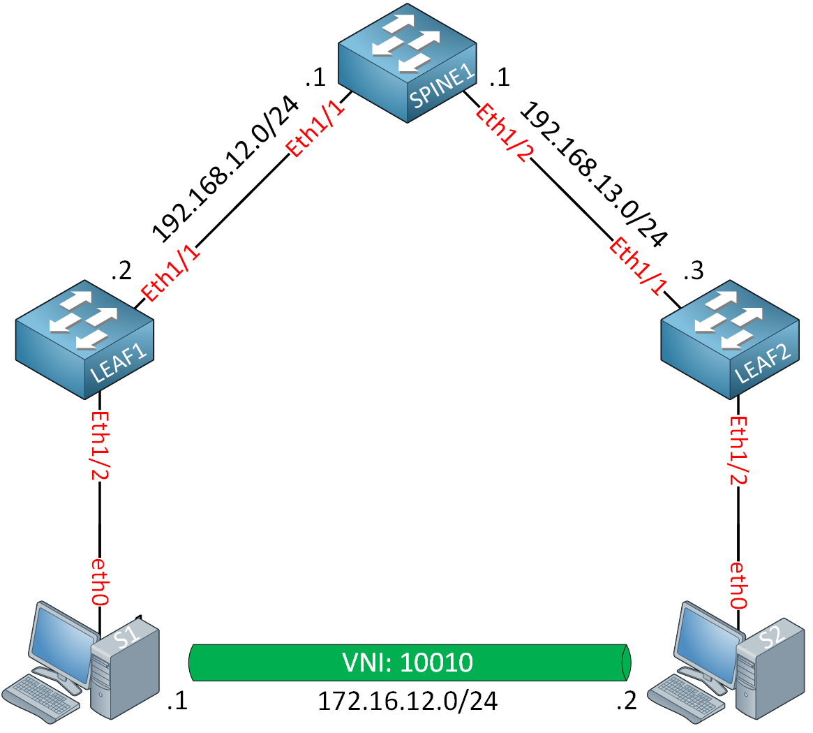
Instead of directly connecting the two leaf switches, we’ll add a spine switch in the middle. This spine switch will be our Rendezvous Point (RP) for multicast. The hosts are simple Ubuntu containers. The only thing they need to do is generate some ICMP traffic to test reachability.
I’m using Cisco NX-OS 9000v version 9.3(9) on the switches. This topology requires ~6 vCPUs and ~25GB of RAM.
Underlay Network
Let’s start with the underlay network. We need to configure IP addresses, routing, and multicast.
IP
Let’s start with the IP addresses. I’ll keep it simple and assign an IP address on every switch routed interface. I’m also using static MAC addresses so that it’s easy to debug and do Wireshark captures. Each switch has a loopback interface.
SPINE1
The spine switch needs a loopback that we can use as the RP.
SPINE1(config)# interface Ethernet 1/1
SPINE1(config-if)# no switchport
SPINE1(config-if)# mac-address 0050.c253.1001
SPINE1(config-if)# ip address 192.168.12.1/24
SPINE1(config)# interface Ethernet 1/2
SPINE1(config-if)# no switchport
SPINE1(config-if)# mac-address 0050.c253.1002
SPINE1(config-if)# ip address 192.168.13.1/24SPINE1(config)# interface Loopback 0
SPINE1(config-if)# ip address 1.1.1.1/32LEAF1
The leaf switches require a loopback interface, which we can use for the NVE interface.
LEAF1(config)# interface Ethernet 1/1
LEAF1(config-if)# no switchport
LEAF1(config-if)# mac-address 0050.c253.2001
LEAF1(config-if)# ip address 192.168.12.2/24
LEAF1(config-if)# exit
LEAF1(config)# interface Loopback 0
LEAF1(config-if)# ip address 2.2.2.2/32LEAF2
LEAF2(config)# interface Ethernet 1/1
LEAF2(config-if)# no switchport
LEAF2(config-if)# mac-address 0050.c253.3001
LEAF2(config-if)# ip address 192.168.13.3/24
LEAF2(config)# interface Loopback 0
LEAF2(config-if)# ip address 3.3.3.3/32OSPF
We’ll configure OSPF to advertise all interfaces.
SPINE1, LEAF1 & LEAF2
(config)# feature ospf
(config)# router ospf 1
SPINE1
SPINE1(config)# interface Ethernet 1/1 - 2
SPINE1(config-if-range)# ip ospf network point-to-point
SPINE1(config-if-range)# ip router ospf 1 area 0.0.0.0

SPINE1(config)# interface Loopback 0
SPINE1(config-if)# ip router ospf 1 area 0.0.0.0
LEAF switches
LEAF1 & LEAF2
(config-router)# interface Ethernet 1/1
(config-if)# ip ospf network point-to-point
(config-if)# ip router ospf 1 area 0.0.0.0

(config)# interface Loopback 0
(config-if)# ip router ospf 1 area 0.0.0.0
That takes care of our underlay network routing.
Multicast
There are three things to configure:
- Enable the multicast feature.
- Enable PIM sparse mode on the interfaces.
- Configure the loopback interface of SPINE1 as the static RP.
SPINE1
Let’s enable multicast:
SPINE1(config)# feature pimEnable PIM on all interfaces (including the loopback):
SPINE1(config)# interface Ethernet 1/1 - 2
SPINE1(config-if-range)# ip pim sparse-mode

SPINE1(config)# interface Loopback 0
SPINE1(config-if)# ip pim sparse-mode
And we’ll make SPINE1 the RP:
SPINE1(config)# ip pim rp-address 1.1.1.1LEAF switches
The configuration of the leaf switches is similar:
LEAF1 & LEAF2
(config)# feature pim
(config)# interface Ethernet 1/1
(config-if)# ip pim sparse-mode

(config)# interface Loopback 0
(config-if)# ip pim sparse-mode

(config)# ip pim rp-address 1.1.1.1
This completes the underlay network configuration.
Overlay Network
Let’s configure the overlay network. The configuration is similar to what we did in the VXLAN Static Ingress Replication lesson.
VNI
Let’s configure a VNI and map a VLAN to it. We’ll configure this on both leaf switches:
LEAF1 & LEAF2
(config)# feature vn-segment-vlan-based
(config)# vlan 10
(config-vlan)# vn-segment 10010

(config)# interface Ethernet 1/2
(config-if)# switchport access vlan 10
That’s all we need for the VNI.
NVE
Let’s enable the VXLAN feature:
LEAF1 & LEAF2
(config)# feature nv overlay
Under the NVE interface configuration, we’ll do something different than what we did with static ingress replication:
LEAF1 & LEAF2
(config)# interface nve1
(config-if-nve)# no shutdown
(config-if-nve)# source-interface loopback0

(config-if-nve)# member vni 10010
(config-if-nve-vni)# mcast-group 239.1.1.1
We’ll configure a multicast group (239.1.1.1) here to use for BUM traffic. This completes our configuration.
Verification
Let’s verify our work.
Underlay Network
Let’s make sure the underlay network is configured correctly.
OSPF
We see two OSPF neighbors on the spine switch:
SPINE1# show ip ospf neighbors
 OSPF Process ID 1 VRF default
 Total number of neighbors: 2
 Neighbor ID     Pri State            Up Time  Address         Interface
 2.2.2.2           1 FULL/ -          00:06:19 192.168.12.2    Eth1/1
 3.3.3.3           1 FULL/ -          00:06:26 192.168.13.3    Eth1/2
The leaf switches can reach each other loopback interfaces:
LEAF1# ping 3.3.3.3 source 2.2.2.2
PING 3.3.3.3 (3.3.3.3) from 2.2.2.2: 56 data bytes
64 bytes from 3.3.3.3: icmp_seq=0 ttl=253 time=4.016 ms
64 bytes from 3.3.3.3: icmp_seq=1 ttl=253 time=2.676 ms
64 bytes from 3.3.3.3: icmp_seq=2 ttl=253 time=2.321 ms
64 bytes from 3.3.3.3: icmp_seq=3 ttl=253 time=2.325 ms
64 bytes from 3.3.3.3: icmp_seq=4 ttl=253 time=3.029 ms
Multicast
The spine switch sees two PIM neighbors:
SPINE1# show ip pim neighbor
PIM Neighbor Status for VRF "default"
Neighbor        Interface            Uptime    Expires   DR       Bidir-  BFD    ECMP Redirect
                                                         Priority Capable State     Capable
192.168.12.2    Ethernet1/1          00:17:43  00:01:26  1        yes     n/a     no
192.168.13.3    Ethernet1/2          00:17:43  00:01:31  1        yes     n/a     no
And the leaf switches see SPINE1 as the RP:
LEAF1# show ip pim rp
PIM RP Status Information for VRF "default"
BSR disabled
Auto-RP disabled
BSR RP Candidate policy: None
BSR RP policy: None
Auto-RP Announce policy: None
Auto-RP Discovery policy: None

RP: 1.1.1.1, (0),
 uptime: 00:57:59   priority: 255,
 RP-source: (local),
 group ranges:
 224.0.0.0/4
LEAF2# show ip pim rp
PIM RP Status Information for VRF "default"
BSR disabled
Auto-RP disabled
BSR RP Candidate policy: None
BSR RP policy: None
Auto-RP Announce policy: None
Auto-RP Discovery policy: None
RP: 1.1.1.1, (0),
uptime: 00:58:08 priority: 255,
RP-source: (local),
group ranges:
224.0.0.0/4The underlay network seems to work correctly.
NVE Interfaces
Let’s check the NVE interface:
LEAF1(config-if-nve)# show nve vni
Codes: CP - Control Plane        DP - Data Plane
       UC - Unconfigured         SA - Suppress ARP
       S-ND - Suppress ND
       SU - Suppress Unknown Unicast
       Xconn - Crossconnect
       MS-IR - Multisite Ingress Replication
       HYB - Hybrid IRB mode

Interface VNI      Multicast-group   State Mode Type [BD/VRF]      Flags
--------- -------- ----------------- ----- ---- ------------------ -----
nve1      10010    239.1.1.1         Up    DP   L2 [10]
This tells us that we use VNI 10010 and multicast group 239.1.1.1. The state is up, and we use data plane learning. We see the same thing on LEAF2:
LEAF2(config-if-nve)# show nve vni
Codes: CP - Control Plane        DP - Data Plane
       UC - Unconfigured         SA - Suppress ARP
       S-ND - Suppress ND
       SU - Suppress Unknown Unicast
       Xconn - Crossconnect
       MS-IR - Multisite Ingress Replication
       HYB - Hybrid IRB mode

Interface VNI      Multicast-group   State Mode Type [BD/VRF]      Flags
--------- -------- ----------------- ----- ---- ------------------ -----
nve1      10010    239.1.1.1         Up    DP   L2 [10]
The two leaf switches don’t know about each other yet:
LEAF1(config-if-nve)# show nve peer
LEAF2(config-if-nve)# show nve peer
This makes sense because there hasn’t been any traffic between hosts yet.
Multicast
Here’s what the multicast routing table looks like on SPINE1:
SPINE1# show ip mroute 239.1.1.1
IP Multicast Routing Table for VRF "default"

(*, 239.1.1.1/32), uptime: 00:01:40, pim ip
  Incoming interface: loopback0, RPF nbr: 1.1.1.1
  Outgoing interface list: (count: 2)
    Ethernet1/2, uptime: 00:01:00, pim
    Ethernet1/1, uptime: 00:01:40, pim


(2.2.2.2/32, 239.1.1.1/32), uptime: 00:01:29, pim mrib ip
  Incoming interface: Ethernet1/1, RPF nbr: 192.168.12.2, internal
  Outgoing interface list: (count: 1)
    Ethernet1/2, uptime: 00:01:00, pim


(3.3.3.3/32, 239.1.1.1/32), uptime: 00:00:32, pim mrib ip
  Incoming interface: Ethernet1/2, RPF nbr: 192.168.13.3, internal
  Outgoing interface list: (count: 1)
    Ethernet1/1, uptime: 00:00:32, pim
We see two sources for multicast group 239.1.1.1:
- 2.2.2.2 (LEAF1)
- 3.3.3.3 (LEAF2)
Here are the multicast routing tables of the leaf switches:
LEAF1# show ip mroute 239.1.1.1
IP Multicast Routing Table for VRF "default"

(*, 239.1.1.1/32), uptime: 00:15:18, nve ip pim
  Incoming interface: Ethernet1/1, RPF nbr: 192.168.12.1
  Outgoing interface list: (count: 1)
    nve1, uptime: 00:15:18, nve


(2.2.2.2/32, 239.1.1.1/32), uptime: 00:15:18, nve mrib ip pim
  Incoming interface: loopback0, RPF nbr: 2.2.2.2
  Outgoing interface list: (count: 1)
    Ethernet1/1, uptime: 00:14:26, pim
LEAF1 has a * entry and one for its own IP address (2.2.2.2). We see a similar output on LEAF2:
LEAF2# show ip mroute 239.1.1.1
IP Multicast Routing Table for VRF "default"

(*, 239.1.1.1/32), uptime: 00:15:09, nve ip pim
  Incoming interface: Ethernet1/1, RPF nbr: 192.168.13.1
  Outgoing interface list: (count: 1)
    nve1, uptime: 00:15:09, nve


(3.3.3.3/32, 239.1.1.1/32), uptime: 00:15:09, nve mrib ip pim
  Incoming interface: loopback0, RPF nbr: 3.3.3.3
  Outgoing interface list: (count: 1)
    Ethernet1/1, uptime: 00:14:14, pim
Traffic between hosts
This is what you came for. Let’s figure out if we can send a ping from S1 to S2:
Hello Amit
Strictly speaking, you don’t need to enable PIM sparse mode on the loopbacks of the devices you are using. However, in the specific topology, Rene has chosen to use the loopback interface of the spine switch as the address of the RP. This is typically best practice as you can see from this lesson here. So for this particular case, if you don’t enable PIM sparse mode on the loopback, it cannot participate as the RP of the topology.
I hope this has been helpful!
Laz
Hi,
Why we need to specify “ip ospf network point-to-point”?
Thanks
Technically it would work without.
By default, OSPF uses the broadcast network type on Ethernet interfaces. This means it will do a DR/BDR election.
This isn’t needed because we only have p2p links in between spine and leaf switches. The LSDB will also be smaller.
For a lab in doesn’t matter but for a large spine and leaf topology, it does. Here is some more info:
https://networklessons.com/vxlan/vxlan-underlay-ospf