Lesson Contents
The embedded RP feature that works for IPv6 multicast is a cool trick that embeds the IPv6 address of the RP within the IPv6 multicast group address. By doing this, multicast-enabled routers can extract the RP address just by looking at the multicast group address and using it for a shared tree. The only router where you have to configure the RP address is on the RP itself…that’s it!
There is one problem however…how are we going to fit a 128-bit IPv6 address of the RP within a 128-bit multicast group address? It doesn’t fit! To get around this problem, we have to use some form of compression.
In this lesson, I will show you what the embedded RP address looks like, and how to create one yourself and we will configure a small network to use this feature.
This is what the embedded RP address looks like:

This picture doesn’t tell you much, so let me explain what everything means:
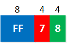
- The first 8 blue bits called “M” define the type of IPv6 address, we are using multicast which means that the first 8 bits have to be set at 1111 1111. In hexadecimal this is “FF”.
- The next 4 red bits, called “F,” are for the flags. When we use the embedded RP feature, we have to set these bits to 0111. In hexadecimal, this is “7”. This is a great identifier when looking at an IPv6 multicast address. When you see the “7” at this position, you know we are dealing with an embedded RP address.
- The four green bits called “S” are the scope. You can use this to define if your multicast traffic should be routed or not, kept within your network, or if it can be used globally. We have some options that we can choose from here:
- Interface-Local scope (1)
- Link-Local scope (2)
- Admin-Local scope (4)
- Site-Local scope (5)
- Organization-Local scope (8)
- Global scope (E)
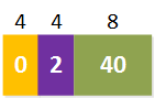
- The 4 yellow bits called “R” are reserved bits. These are always set to 0.
- The 4 purple bits called “I” is the RP interface identifier. We take the last 4 bits of the IPv6 address that we will use as the RP and add those here.
- The 8 olive green bits called “H” is the prefix length in hexadecimal. When you have a prefix length of 64 bits, you will add “40” here. (64 in decimal = 40 in hexadecimal).
- The 64 dark blue bits called “P” is the prefix of the IPv6 address that we use as the RP.
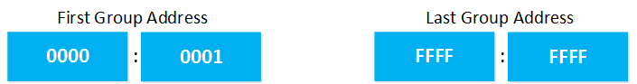
- The last 32 light blue bits called “G” is to define the multicast group address. With 32 bits, this means our first group address will be 0000:0001, and the last group address is FFFF:FFFF.
To understand how to create your own embedded RP address, it’s best to look at an actual example. Let’s imagine we want to use the IPv6 address FC00:2:2:2::2 /64 as our RP. What will the embedded RP address look like? I’ll break it down for you:
- The first 8 bits are FF because we have a multicast address.
- The flags are set to 7 because we use the embedded RP feature.
- The scope is set to organization-local scope. You can pick whatever you like.
- The reserved bits are set to 0. We can’t choose anything else here.
- The RP interface ID is set to 2. These are the last 4 bits of our RP IPv6 address (FC00:2:2:2::2).
- The prefix length is set to 40 since we are using a prefix length of /64. 64 in decimal is 40 in hexadecimal.

- The prefix of our RP IPv6 address is FC00:2:2:2, so we can add it here.
- With 32 bits, there are a lot of group addresses you can use. The first group address starts at 0000:0001, and the last group address is FFFF:FFFF.
The complete embedded RP address will look like this:

I used the first available group address in this example. Are you following me so far? Let’s configure a small network and use the addresses that I just showed you!
Configuration
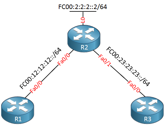
To demonstrate the embedded RP, I will use a small network with three routers. R2 will be the embedded RP using the IPv6 address on its loopback, R1 will join a multicast group address, and R3 will send some traffic to this address. For connectivity, we will use OSPFv3. Here’s what it looks like:
The first thing we should do is enable unicast and multicast routing for IPv6 on all routers:
R1, R2 & R3:
(config)#ipv6 unicast-routing
(config)#ipv6 multicast-routing
Let’s add some IPv6 addresses:
R1(config)#interface fastEthernet 0/0
R1(config-if)#ipv6 address fc00:12:12:12::1/64R2(config)#interface FastEthernet 0/0
R2(config-if)#ipv6 address fc00:12:12:12::2/64
R2(config-if)#interface FastEthernet f0/1
R2(config-if)#ipv6 address fc00:23:23:23::2/64
R2(config)#interface loopback 0
R2(config-if)#ipv6 address fc00:2:2:2::2/64R3(config)#interface FastEthernet 0/0
R3(config-if)#ipv6 address fc00:23:23:23::3/64To make sure R1 and R3 know how to reach the RP, we will add OSPFv3:
Hi Rene,
I tried to simulate the Embedded-RP but it didn’t work.
The only stuff that worked was statically configured ipv6 pim rp-address on all the nodes.
But i was trying to check that cool feature and what i saw is that on DR (where source is connected) there’s a constant Registering appears there and RP node itself is not seeing (S,G), only (*,G) as a part of connected receiver via MLD join-group.
I don’t get what i’m missing here…
I will be very thankful to you if you can reply with your suggestions what could be the problem?
By the way does this feature s
... Continue reading in our forumVladimir,
I am pretty sure that an Embedded RP will work on that platform. One key configuration step that I didn’t see you mention is that you must manually configured the chosen RP to be an RP for itself, via the ipv6 pim rp-address command.
After the RP has been statically configured to itself, your embedded RP address (assuming it is configured correctly!) should work.
You are correct in that if you are using a /128 loop back address, you would need to change the “40” to an “80” since those two digits represent the mask in hexadecimal.
If this still doesn’
... Continue reading in our forumHello Andrew,
I already attached the configuration with couple of MCAST outputs for all the devices and topology as well. Attaching it again.
I did configure the ipv6 pim rp-address on the device that is having that ipv6 address configured on the loopback (R2-RR).
I really got confused why this is not working…If required, please post what additional outputs you need from my side
Couple of additional queries:
Regarding the format of MCAST group IPv6 address with embedded RP:
FF7<Scope>:0<RP Interface ID><HEX prefix Lenght>:<64 bit RP Prefix>:<32 bit group ID>
Do
... Continue reading in our forumI looked at the formation of your Embedded RP, and it looks correct.
Your RP = FC00:2:2:2::2/64
Your Embedded RP Address: FF78:240:FC00:2:2:2:0:1. This address is correctly formatted assuming you want to use the first multicast group (then trailing 0:1) possible on that RP, and the scope of the multicast group is global (8).
Also, your show commands have the correct output (like on the RP, for example) where it shows the correct (*,G) entry.
The problem is your lab is extremely complicated, and frankly, I don’t want to spend two hours troubleshooting it. I su
... Continue reading in our forumHi Andrew,
I checked with 3 nodes R1—R2—R3 and it worked properly. R1 (source), R2 (RP) and R3 (receiver)
What i don’t understand is if R1 is sending the MCAST traffic, then who is DR in this scenario? R2? Who actually is sending the unicast register messages towards RP? A little bit confusing this scenario.
I’m regular to some basic setup where R5—R1—R2—R3—R7 where (R5 is a source), (R1 a DR), (R2 is and RP), (R3 is a last hop router connected to receiver), (R7 is a receiver)
But what i found out is if i test with 5 devices than it’s not working and DR is show
... Continue reading in our forum