Lesson Contents
In previous DMVPN lessons I explained how to configure a small DMVPN network using a hub and two spoke routers. The disadvantage of a single hub router is that it’s a single point of failure. Once your hub router fails, the entire DMVPN network is gone.
To add redundancy to our DMVPN network we need to add another hub router. There are two options for this:
-
- Dual hub – Single Cloud
- Dual hub – Dual Cloud
With the single cloud option we use a single DMVPN network but we add a second hub. The spoke routers will use only one multipoint GRE interface where we configure the second hub as a next hop server.
The dual cloud option also has two hubs but we will use two DMVPN networks which means that all spoke routers will get a second multipoint GRE interface.
In this lesson we’ll take a look at the dual hub single cloud option. Take a look at the following picture:
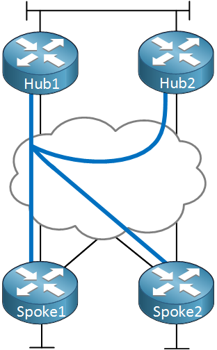
Above you can see a DMVPN network with two hubs and two spoke routers. Hub1 will be the primary hub, hub2 is the secondary hub. We use a single DMVPN network, each router only has one multipoint GRE interface.
The advantage of this setup is that it’s very easy to implement. The configuration of hub2 is similar to hub1. On the spoke routers we only have to add the second router as a hub.
The disadvantage is that we have limited control when it comes to routing. Since we use a single multipoint GRE interface, it’s difficult to make the spoke routers prefer one hub over another.
Let’s take a look at the configuration and you’ll see the advantages and disadvantages in action…
Configurations
Here’s the topology we will use:
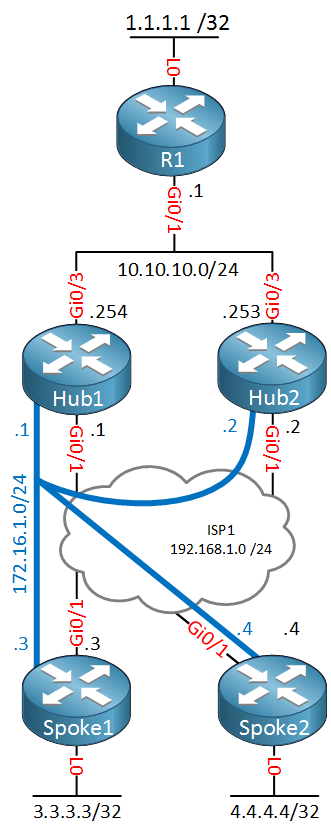
Above we have five routers. On top we have R1 which is located on the main site where we use the 10.10.10.0/24 subnet. Behind R1 we have a loopback interface with IP address 1.1.1.1/32.
The two hub routers and spoke routers are connected to the Internet. Normally you would connect the two hub routers to different ISPs and we would use public IP addresses. To keep it simple, I connected all routers to the 192.168.1.0/24 subnet.
Each spoke router has a loopback interface with an IP address.
The DMVPN network will use subnet 172.16.1.0/24 where hub1 will be the primary hub. Spoke routers will register themselves with both hub routers.
Hub Routers
Let’s start with the hub1 router:
Hub1(config)#interface Tunnel 0
Hub1(config-if)#ip address 172.16.1.1 255.255.255.0
Hub1(config-if)#ip nhrp authentication DMVPN
Hub1(config-if)#ip nhrp map multicast dynamic
Hub1(config-if)#ip nhrp network-id 1
Hub1(config-if)#tunnel source GigabitEthernet 0/1
Hub1(config-if)#tunnel mode gre multipoint
The configuration above is a basic DMVPN hub configuration that I have used in all my examples so far. Let’s configure the hub2 router:
Hub2(config)#interface Tunnel 0
Hub2(config-if)#ip address 172.16.1.2 255.255.255.0
Hub2(config-if)#ip nhrp authentication DMVPN
Hub2(config-if)#ip nhrp map multicast dynamic
Hub2(config-if)#ip nhrp network-id 1
Hub2(config-if)#tunnel source GigabitEthernet 0/1
Hub2(config-if)#tunnel mode gre multipoint
The configuration above is exactly the same as the hub1 router (except for the IP address). However there is one more thing left to do on the hub2 router:
Hub2(config)#interface Tunnel 0
Hub2(config-if)#ip nhrp map 172.16.1.1 192.168.1.1
Hub2(config-if)#ip nhrp map multicast 192.168.1.1
Hub2(config-if)#ip nhrp nhs 172.16.1.1
The hub2 router is a hub but will also be a client of the hub1 router. This is required when we want to configure a routing protocol like OSPF. The hub1 router will be the DR of our DMVPN network and it will require a neighbor adjacency with all routers, including the hub2 router. Hold this thought for now, we’ll configure OSPF in a bit…
Spoke routers
Let’s start with the spoke1 router:
Spoke1(config)#interface Tunnel 0
Spoke1(config-if)#ip address 172.16.1.3 255.255.255.0
Spoke1(config-if)#ip nhrp authentication DMVPN
Spoke1(config-if)#ip nhrp map 172.16.1.1 192.168.1.1
Spoke1(config-if)#ip nhrp map 172.16.1.2 192.168.1.2
Spoke1(config-if)#ip nhrp map multicast 192.168.1.1
Spoke1(config-if)#ip nhrp map multicast 192.168.1.2
Spoke1(config-if)#ip nhrp network-id 1
Spoke1(config-if)#ip nhrp nhs 172.16.1.1
Spoke1(config-if)#ip nhrp nhs 172.16.1.2
Spoke1(config-if)#tunnel source GigabitEthernet 0/1
Spoke1(config-if)#tunnel mode gre multipoint
The configuration above is a basic DMVPN spoke configuration. The only difference is that we included the following additional three commands for the hub2 router:
- ip nhrp map 172.16.1.2 192.168.1.2
- ip nhrp map multicast 192.168.1.2
- ip nhrp nhs 172.16.1.2
By adding these three commands, our spoke routers can use a second hub router. This makes it very easy to add redundancy to our DMVPN network.
Let’s do the same thing on the spoke2 router:
Spoke2(config)#interface Tunnel0
Spoke2(config-if)#ip address 172.16.1.4 255.255.255.0
Spoke2(config-if)#no ip redirects
Spoke2(config-if)#ip nhrp authentication DMVPN
Spoke2(config-if)#ip nhrp map 172.16.1.1 192.168.1.1
Spoke2(config-if)#ip nhrp map 172.16.1.2 192.168.1.2
Spoke2(config-if)#ip nhrp map multicast 192.168.1.1
Spoke2(config-if)#ip nhrp map multicast 192.168.1.2
Spoke2(config-if)#ip nhrp network-id 1
Spoke2(config-if)#ip nhrp nhs 172.16.1.1
Spoke2(config-if)#ip nhrp nhs 172.16.1.2
Spoke2(config-if)#tunnel source GigabitEthernet0/1
Spoke2(config-if)#tunnel mode gre multipoint
Let’s see if our configuration is correct:
Hub1#show dmvpn | begin Peers
Type:Hub, NHRP Peers:3,

 # Ent  Peer NBMA Addr Peer Tunnel Add State  UpDn Tm Attrb
 ----- --------------- --------------- ----- -------- -----
     1 192.168.1.2          172.16.1.2    UP 00:00:31     D
     1 192.168.1.3          172.16.1.3    UP 00:00:34     D
1 192.168.1.4 172.16.1.4 UP 00:00:29 DHub2#show dmvpn | begin Peers
Type:Hub/Spoke, NHRP Peers:3,
# Ent Peer NBMA Addr Peer Tunnel Add State UpDn Tm Attrb
----- --------------- --------------- ----- -------- -----
1 192.168.1.1 172.16.1.1 UP 00:00:45 S
1 192.168.1.3 172.16.1.3 UP 00:00:41 D
1 192.168.1.4 172.16.1.4 UP 00:00:43 DAbove you can see that the hub1 router has three dynamic NHRP registrations, the two spoke routers and hub2.
The hub2 router has two dynamic registrations, one for each spoke router.
We can also verify this from the spoke routers:
Spoke1#show dmvpn | begin Peers
Type:Spoke, NHRP Peers:2,

 # Ent  Peer NBMA Addr Peer Tunnel Add State  UpDn Tm Attrb
 ----- --------------- --------------- ----- -------- -----
     1 192.168.1.1          172.16.1.1    UP 00:01:41     S
1 192.168.1.2 172.16.1.2 UP 00:01:35 SSpoke2#show dmvpn | begin Peers
Type:Spoke, NHRP Peers:2,
# Ent Peer NBMA Addr Peer Tunnel Add State UpDn Tm Attrb
----- --------------- --------------- ----- -------- -----
1 192.168.1.1 172.16.1.1 UP 00:01:43 S
1 192.168.1.2 172.16.1.2 UP 00:01:43 SOur DMVPN network is up and running. Let’s configure a routing protocol…I’ll pick OSPF since it’s a good example to demonstrate the disadvantage of the single cloud option.
OSPF
We will use two areas for this network. Between R1, hub1 and hub2 we will use area 0. The DMVPN network will use area 1. Let’s start with the backbone area:
R1(config)#router ospf 1
R1(config-router)#network 10.10.10.0 0.0.0.255 area 0
R1(config-router)#network 1.1.1.1 0.0.0.0 area 0Hub1(config)#router ospf 1
Hub1(config-router)#network 10.10.10.0 0.0.0.255 area 0Hub2(config)#router ospf 1
Hub2(config-router)#network 10.10.10.0 0.0.0.255 area 0Now we can configure the DMVPN network. Make sure the hub1 router becomes the DR and hub2 the BDR. The spoke routers should never be elected as DR/BDR:
Hub1(config)#interface Tunnel 0
Hub1(config-if)#ip ospf network broadcast
Hub1(config-if)#ip ospf priority 2

Hub1(config)#router ospf 1
Hub1(config-router)#network 172.16.1.0 0.0.0.255 area 1Hub2(config)#interface Tunnel 0
Hub2(config-if)#ip ospf network broadcast
Hub2(config-if)#ip ospf priority 1
Hub2(config)#router ospf 1
Hub2(config-router)#network 172.16.1.0 0.0.0.255 area 1Spoke1(config)#interface Tunnel 0
Spoke1(config-if)#ip ospf priority 0
Spoke1(config-if)#ip ospf network broadcast
Spoke1(config)#router ospf 1
Spoke1(config-router)#network 172.16.1.0 0.0.0.255 area 1
Spoke1(config-router)#network 3.3.3.3 0.0.0.0 area 1Spoke2(config)#interface Tunnel 0
Spoke2(config-if)#ip ospf priority 0
Spoke2(config-if)#ip ospf network broadcast
Spoke2(config)#router ospf 1
Spoke2(config-router)#network 172.16.1.0 0.0.0.255 area 1
Spoke2(config-router)#network 4.4.4.4 0.0.0.0 area 1That takes care of the OSPF configuration. Let’s verify our work:
Spoke1#show ip ospf neighbor

Neighbor ID     Pri   State           Dead Time   Address         Interface
192.168.1.1       2   FULL/DR         00:00:38    172.16.1.1      Tunnel0
192.168.1.2 1 FULL/BDR 00:00:33 172.16.1.2 Tunnel0Spoke2#show ip ospf neighbor
Neighbor ID Pri State Dead Time Address Interface
192.168.1.1 2 FULL/DR 00:00:39 172.16.1.1 Tunnel0
192.168.1.2 1 FULL/BDR 00:00:36 172.16.1.2 Tunnel0Above we can see that the spoke routers see hub1 as the DR and hub2 as the BDR. Let’s take a look at the routes that we learned:
R1#show ip route ospf

      3.0.0.0/32 is subnetted, 1 subnets
O IA     3.3.3.3 [110/1002] via 10.10.10.254, 00:03:44, GigabitEthernet0/1
                 [110/1002] via 10.10.10.253, 00:01:44, GigabitEthernet0/1
      4.0.0.0/32 is subnetted, 1 subnets
O IA     4.4.4.4 [110/1002] via 10.10.10.254, 00:03:44, GigabitEthernet0/1
                 [110/1002] via 10.10.10.253, 00:01:44, GigabitEthernet0/1
      172.16.0.0/24 is subnetted, 1 subnets
O IA     172.16.1.0 [110/1001] via 10.10.10.254, 00:03:44, GigabitEthernet0/1
                    [110/1001] via 10.10.10.253, 00:01:44, GigabitEthernet0/1
R1 is seeing two equal cost paths. What about the hub routers?
Hub1#show ip route ospf

      1.0.0.0/32 is subnetted, 1 subnets
O        1.1.1.1 [110/2] via 10.10.10.1, 00:04:26, GigabitEthernet0/2
      3.0.0.0/32 is subnetted, 1 subnets
O        3.3.3.3 [110/1001] via 172.16.1.3, 00:04:26, Tunnel0
      4.0.0.0/32 is subnetted, 1 subnets
O 4.4.4.4 [110/1001] via 172.16.1.4, 00:04:26, Tunnel0Hub2#show ip route ospf
1.0.0.0/32 is subnetted, 1 subnets
O 1.1.1.1 [110/2] via 10.10.10.1, 00:04:45, GigabitEthernet0/2
3.0.0.0/32 is subnetted, 1 subnets
O 3.3.3.3 [110/1001] via 172.16.1.3, 00:02:36, Tunnel0
4.0.0.0/32 is subnetted, 1 subnets
O 4.4.4.4 [110/1001] via 172.16.1.4, 00:02:36, Tunnel0The hub routers will use their own tunnel interfaces to reach the spoke routers.
Let’s check spoke1 and spoke2:
Spoke1#show ip route ospf

      1.0.0.0/32 is subnetted, 1 subnets
O IA     1.1.1.1 [110/1002] via 172.16.1.2, 00:01:50, Tunnel0
                 [110/1002] via 172.16.1.1, 00:05:01, Tunnel0
      4.0.0.0/32 is subnetted, 1 subnets
O        4.4.4.4 [110/1001] via 172.16.1.4, 00:04:51, Tunnel0
O IA  10.10.10.0/24 [110/1001] via 172.16.1.2, 00:01:50, Tunnel0
[110/1001] via 172.16.1.1, 00:05:01, Tunnel0Spoke2#show ip route ospf
1.0.0.0/32 is subnetted, 1 subnets
O IA 1.1.1.1 [110/1002] via 172.16.1.2, 00:02:06, Tunnel0
[110/1002] via 172.16.1.1, 00:05:17, Tunnel0
3.0.0.0/32 is subnetted, 1 subnets
O 3.3.3.3 [110/1001] via 172.16.1.3, 00:05:07, Tunnel0
O IA 10.10.10.0/24 [110/1001] via 172.16.1.2, 00:02:06, Tunnel0
[110/1001] via 172.16.1.1, 00:05:17, Tunnel0The spoke routers have two equal cost paths through the hub1 and hub2 routers.
What if we want to use hub1 as the primary router and hub2 only as a backup? Perhaps hub1 is connected to a fast dedicated internet connection and hub2 is using a slow backup DSL connection.
This can be a challenge…traffic from R1 towards the spoke routers is no problem but the other way around will be. Let me show you:
Hi This is an excellent article.
But I have one quesion.
Is it Ok that HUBs and SPOKEs network-id is different?
All interfaces that belong to the same DMVPN network should use the same network ID. I just fixed it, that was a copy/paste error
Very useful lesson.
Thanks Rene.
I think below can be control the route also
For OSPF, if the Hub network is redistributed will be easy as Hub 1 can advertised as E1 and Hub 2 advertised as E2.
For EIGRP, Hub2 also can use AD or Metric to manipulate the route for Spoke.
Davis
Hi Davis,
You could use redistribution to influence how the spoke routers reach R1 on top. Hub1 could advertise regular OSPF routes and hub2 could redistribute these routes.
Getting from the hubs to the spoke routers is harded though, the spoke routes are advertising the same info to both hub routers.
EIGRP is a bit more flexible than OSPF.
Rene
Thanks Rene.
Davis