Perhaps you have heard about the term “wire speed” before. It’s something the marketing department likes to use when it comes to selling networking equipment. It means that packets can be forwarded without any noticeable delay. Everything that I explain in this lesson about multilayer switches also applies to routers. Let’s take a look at the difference between layer two and multilayer switches from the switch’s perspective:
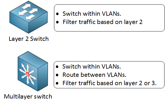
You know that layer two switches only will switch Ethernet frames within a VLAN, and if we want we can filter traffic based on layer two (for example with port-security). The multilayer switch can do the same but is also able to route between VLANs and filter on layers three or four using access lists.
Forwarding on layer two is based on the destination MAC address. Our switch learns the source MAC addresses on incoming frames, and it builds the MAC address table. Whenever an Ethernet frame enters one of our interfaces, we’ll check the MAC address table to find the destination MAC address, and we’ll send it out to the correct interface.
Forwarding on layer three is based on the destination IP address. Forwarding happens when the switch receives an IP packet where the source IP address is in a different subnet than the destination IP address.
When our multilayer switch receives an IP packet with its own MAC address as the destination in the Ethernet header, there are two possibilities:
- If the destination IP address is an address that is configured on the multilayer switch, then the IP packet was destined for this switch.
- If the destination IP address is an address that is not configured on the multilayer switch, then we have to act as a gateway and “route” the packet. This means we’ll have to do a lookup in the routing table to check for the longest match. Also, we have to check if the IP packet is allowed if you configured an ACL.
Back in the days…switching was done at hardware speed while routing was done in software. Nowadays, both switching and routing are done at hardware speed. In the remaining of this lesson, you’ll learn why.
Let’s take a look at the difference between handling Ethernet Frames and IP Packets:
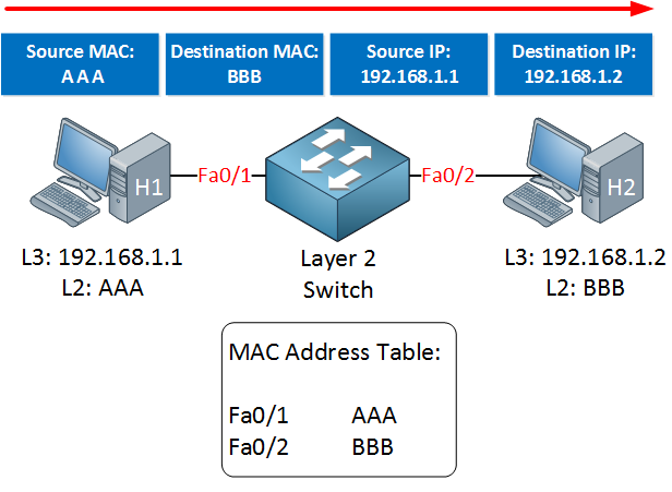
The life of a layer two switch is simple:
- The switch will verify the checksum of the Ethernet frame to make it sure it’s not corrupted or altered.
- The switch receives an Ethernet frame and adds the source MAC address to the MAC address table.
- The switch forwards the Ethernet frame to the correct interface if it knows the destination MAC address. If not, it will be flooded.
There is no alteration of the Ethernet frame!
Now, let’s see what we have to do when we receive an IP packet on a multilayer switch:
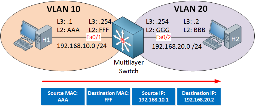
In the example above, H1 is sending an IP packet towards H2. Note that they are in different subnets, so we will have to route it. When our multilayer switch receives the IP packet, this is what will happen:
- The switch will verify the checksum of the Ethernet frame to make it sure it’s not corrupted or altered.
- The switch will verify the checksum of the IP packet to make it sure it’s not corrupted or altered.
The multilayer switch will check the routing table, notices that 192.168.20.0/24 is directly connected, and the following will happen:
- Check the ARP table to see if there’s a layer two to 3 mapping for H2. If there is no mapping, the multilayer switch will send an ARP request.
- The destination MAC address changes from FFF (Multilayer switch Fa0/1 ) to BBB (H2).
- The source MAC address changes from AAA (H1) to GGG (Multilayer switch Fa0/2).
- The TTL (time to live) field in the IP packet is decreased by one, and because of this, the IP header checksum will be recalculated.
- The Ethernet frame checksum must be recalculated.
- The Ethernet frame carrying the IP packet will be sent out of the interface towards H2.
As you can see, there are quite some steps involved if we want to route IP packets.
When we look at multilayer switches, there is a “separation of duties”. We have to build a table for the MAC addresses, fill a routing table, ARP requests, check if an IP packet matches an access-list, etc, and we need to forward our IP packets. These tasks are divided between the “control plane” and the “data plane”. Let me give you an illustration:
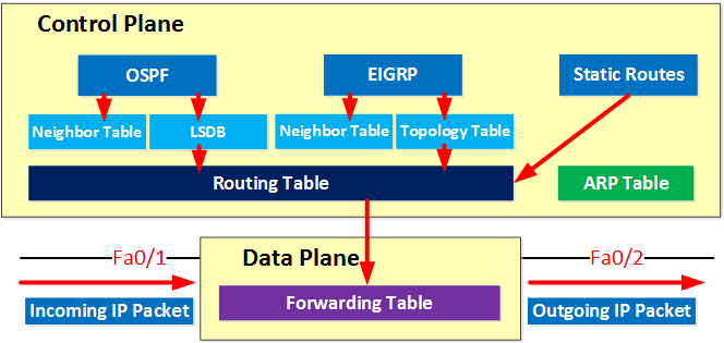
The control plane is responsible for exchanging routing information using routing protocols and building a routing table and ARP table. The data plane is responsible for the actual forwarding of IP packets. The routing table isn’t very suitable for fast forwarding because we have to deal with recursive routing. What is recursive routing? Let me give you an example:
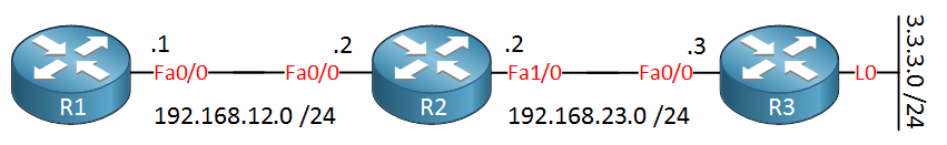
In the example above, I have three routers. R3 has a loopback interface that we want to reach from R1. I will use static routes for reachability:
R1(config)#ip route 3.3.3.0 255.255.255.0 192.168.23.3
R1(config)#ip route 192.168.23.0 255.255.255.0 192.168.12.2
The first static route is to reach the loopback0 interface of R3 and points to the FastEthernet0/0 interface of R3. The second static route is required to reach network 192.168.23.0/24.
R1#show ip route
Codes: C - connected, S - static, R - RIP, M - mobile, B - BGP
       D - EIGRP, EX - EIGRP external, O - OSPF, IA - OSPF inter area
       N1 - OSPF NSSA external type 1, N2 - OSPF NSSA external type 2
       E1 - OSPF external type 1, E2 - OSPF external type 2
       i - IS-IS, su - IS-IS summary, L1 - IS-IS level-1, L2 -IS-IS level-2
       ia - IS-IS inter area, * - candidate default, per-user static route
       o - ODR, P - periodic downloaded static route

Gateway of last resort is not set

C    192.168.12.0/24 is directly connected, FastEthernet0/0
     3.0.0.0/24 is subnetted, 1 subnets
S       3.3.3.0 [1/0] via 192.168.23.3
S    192.168.23.0/24 [1/0] via 192.168.12.2
Whenever R1 wants to reach 3.3.3.0/24, we have to do three lookups:
- The first lookup is to check the entry for 3.3.3.0 /24. It’s there, and the next hop IP address is 192.168.23.3
- The second lookup is for 192.168.23.3. There’s an entry, and the next hop IP address is 192.168.12.2.
- The third and last lookup is for 192.168.12.2. There’s an entry, and it is directly connected.
R1 has to check the routing table 3 times before it knows where to send its traffic. That doesn’t sound very efficient, right? Doing multiple lookups to reach a specific network is called recursive routing.
Most of the time, all incoming and outgoing IP packets will be processed and forwarded by the data plane, but there are some exceptions. First let me show you this picture:
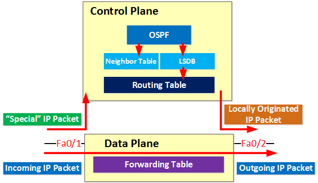
Most of the IP packets can be forwarded by the data plane. However, there are some “special” IP packets that can’t be forwarded by the data plane immediately, and they are sent to the control plane. Here are some examples:
- IP packets destined for one of the IP addresses of the multilayer switch.
- Routing protocol traffic like OSPF, EIGRP, or BGP.
- IP packets that have some of the options set in the IP header.
- IP packets with an expired TTL.
The control plane can forward outgoing IP packets to the data plane or use its forwarding mechanism to determine the outgoing interface and the next hop IP address. An example of this is local policy-based routing.
Our multilayer switch has many more steps to take than the layer two switches, so theoretically, it should be slower, right?
One reason that multilayer switches are able to forward frames and packets at wire speed is because of special hardware called ASICs in the data plane.
Information like MAC addresses, the routing table, or access lists are stored in these ASICs. The tables are stored in content-addressable memory (CAM) and ternary content-addressable memory (TCAM).
- The CAM table is used to store layer two information like:
- The source MAC address.
- The interface where we learned the MAC address.
- To which VLAN the MAC address belongs.
Table lookups are fast! Whenever the switch receives an Ethernet frame, it will use a hashing algorithm to create a “key” for the destination MAC address + VLAN, and it will compare this hash to the already hashed information in the CAM table. This way, it is able to quickly look up information in the CAM table.
- The TCAM table is used to store “higher layer” information like:
- Access-lists.
- Quality of service information.
- Routing table.
- The TCAM table can match on three different values:
- 0 = must be 0.
- 1 = must be 1.
- X = 0 or 1, both acceptable.
- The longest match will return a hit.
- Useful for a lookup where we don’t need an exact match. (routing table or ACLs, for example).
Because there are three values, we call it ternary.
So why are there two types of tables?
When we look for a MAC address, we always require an exact match. We require the exact MAC address to forward an Ethernet frame. The MAC address table is stored in a CAM table.
Whenever we need to match an IP packet against the routing table or an access-list, we don’t always need an exact match. For example, an IP packet with destination address 192.168.20.44 will match:
- 192.168.20.44 /32
- 192.168.20.0 /24
- 192.168.0.0 /16
Information like the routing table is stored in a TCAM table for this reason. We can decide whether all or some bits have to match.
Here’s an example of a TCAM table:
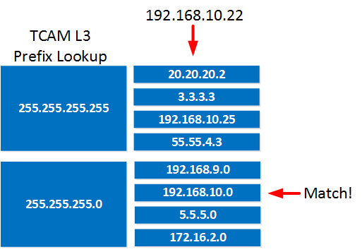
If we want to match IP address 192.168.10.22, the multilayer switch will first see if there’s a “most specific match”. Nothing matches 192.168.10.22 /32, so we’ll continue if there is anything else that matches. In this case, there is an entry that matches 192.168.10.0 /24. The example above applies to routing table lookups, access lists but also quality of service, VLAN access lists, and more.
Now you know all the steps a multilayer switch has to take when it has to forward ip packets, the control/data plane, and that we use different tables stored in special hardware called ASICs. Let’s take a closer look at the actual ‘forwarding’ of IP packets.
There are different switching methods to forward IP packets. Here are the different switching options:
- Process switching:
- All packets are examined by the CPU, and all forwarding decisions are made in software…very slow!
- Fast switching (also known as route caching):
- The first packet in a flow is examined by the CPU; the forwarding decision is cached in hardware for the next packets in the same flow. This is a faster method.
- (CEF) Cisco Express Forwarding (also known as topology-based switching):
- Forwarding table created in hardware beforehand. All packets will be switched using hardware. This is the fastest method but there are some limitations. Multilayer switches and routers use CEF.
When using process switching, the router will remove the header for each Ethernet frame, look for the destination IP address in the routing table for each IP packet, and then forward the Ethernet frame with the rewritten MAC addresses and CRC to the outgoing interface. Everything is done in software, so this is very CPU-intensive.

Wow, great article. Thanks for your work. I knew that there is always a “ip cef” command in the routers, but I never did a deep inspection of that.
Thanks Johannes!
The reason why we need CEF is simple…a router has to perform multiple steps before it can forward a packet…routing table lookup, ARP table lookup, ACLs, etc. If you do all of this in software then it will be very slow. With CEF we put all this information into a single hardware table which allows really fast packet forwarding.
Other vendors do the same thing, CEF is Cisco-only though.
Rene
One small thing that may need to be clarified. CEF isn’t linked to hardware forwarding.
Routers can have both software forwarding with CEF, or it can install the CEF entries into hardware. This is platform dependent - platforms such as the 1800 or 2800 don’t have dedicated forwarding hardware.
Hi Greg,
Thanks for your comment and you are right, this is important to know. I’ll edit the post to mention this.
Rene
Hi Rene,
Thanks. Complex technology explained in simple article and very easy to understand.