In this lesson, we will take a look at how you can create an Etherchannel link over 802.1Q tunneling. If you have no idea how 802.1Q tunneling works, it’s best to read my previous lesson first which covers the basics of 802.1Q tunneling.
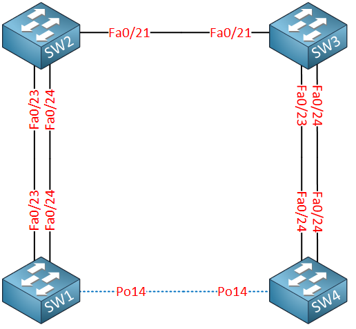
Here’s the topology that I will use:

SW2 and SW3 are the service provider network. SW1 and SW4 belong to the customer and present two different sites. The idea is that we want to create an Etherchannel between SW1 and SW4 over the service provider network. First, we will configure the trunk between SW2 and SW3:
SW2(config)#interface fastEthernet 0/21
SW2(config-if)#switchport trunk encapsulation dot1q
SW2(config-if)#switchport mode trunkSW3(config)#interface fastEthernet 0/21
SW3(config-if)#switchport trunk encapsulation dot1q
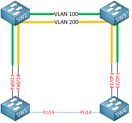
SW3(config-if)#switchport mode trunk Our next move is to configure the interfaces pointing toward the customer switches. To “simulate” that our FastEthernet 0/23 +/24 interfaces on SW1 and SW4 are directly connected to each other we have to use a separate “transit” VLAN for each interface pair. Traffic on the FastEthernet 0/23 interface will flow in service provider VLAN 100, and traffic for FastEthernet 0/24 will use VLAN 200. Take a look at the picture below to visualize this:
If we use a single transit VLAN for all traffic on the FastEthernet 0/23 and 24 interfaces, then we run into issues with our Etherchannel because FastEthernet 0/23 could talk to 0/24 or vice versa.
Here’s the configuration for SW2:
SW2(config)#interface fastEthernet 0/23
SW2(config-if)#switchport access vlan 100
SW2(config-if)#switchport mode dot1q-tunnel
SW2(config-if)#l2protocol-tunnel point-to-point pagpSW2(config)#interface fastEthernet 0/24
SW2(config-if)#switchport access vlan 200
SW2(config-if)#switchport mode dot1q-tunnel
SW2(config-if)#l2protocol-tunnel point-to-point pagp The magic bullet that makes the etherchannel possible is the l2protocol-tunnel command and specifying PAgP or LACP. The configuration for SW3 is similar:
SW3(config)#interface fastEthernet 1/0/23
SW3(config-if)#switchport access vlan 100
SW3(config-if)#switchport mode dot1q-tunnel
SW3(config-if)#l2protocol-tunnel point-to-point pagpSW3(config)#interface fastEthernet 0/24
SW3(config-if)#switchport access vlan 200
SW3(config-if)#switchport mode dot1q-tunnel
SW3(config-if)#l2protocol-tunnel point-to-point pagpOur service provider switches are now ready; the configuration on the customer switches is just a regular Etherchannel configuration:


Hello Rene what happens if i have more switches for example SW1 -> SW2 -> SW5 -> SW3 -> SW4.
Will the SW5 switch only need to have vlan 100 and 200 created? and also be in trunk with SW2 and SW3? Like it happens with MPLS VPN Provider Router that only needs to know IGP and dont need to know MP-BGP. I hope you getting my line of thought. Waiting for your reply
Hi Mauro,
That’s right, SW5 would only require VLAN 100 and 200. It’s a like a “P” router in MPLS VPN.
Rene
Hi Rene,
I wonder if you could make a write up for FCoE in NX-OS.
Thanks!
Hi Rene,
But, if you assign a specific customer vlan just for one link, doesn’t that defeat the purpose of building the etherchannel i.o.w to have a redundancy when one link in the channel goes down ?
Hi Edwin,
Yes, in this example there’s still only one link between SW2 and SW3. I’ve only added this example since it’s a topic on the CCIE R&S blueprint.
Rene