802.1Q tunneling (aka Q-in-Q) is often used by Metro Ethernet providers as a layer 2 VPN for customers. 802.1Q (or dot1q) tunneling is pretty simple…the provider will put an 802.1Q tag on all the frames that it receives from a customer with a unique VLAN tag. By using a different VLAN tag for each customer, we can separate the traffic from different customers and also transparently transfer it throughout the service provider network.
One of the advantages of this solution is that it’s easy to implement, you don’t need exotic hardware, and you don’t have to run any routing protocols between the service provider and customer (unlike MPLS VPN). From the customer’s perspective, it’s just like their sites are directly connected on layer 2.
In this lesson, I’m going to show you how to configure 802.1Q tunneling and I’ll explain how it works. I’ll be using the following topology for this:
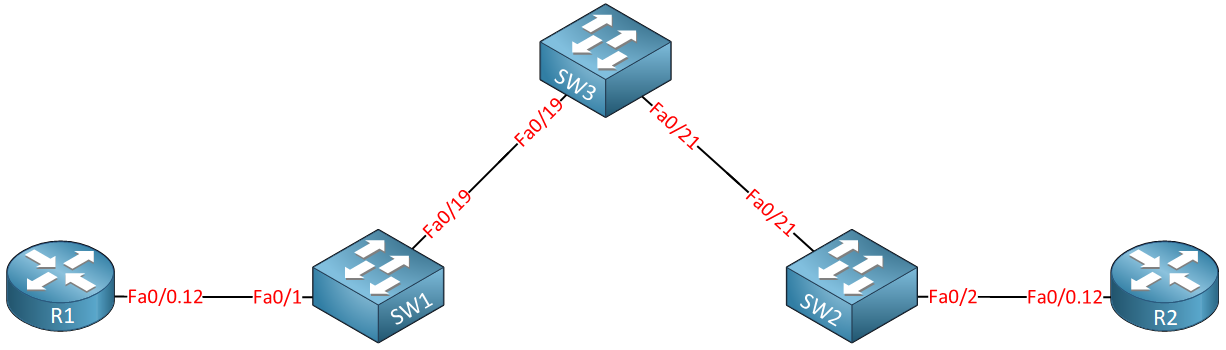
Above you see two routers called R1 and R2, imagine these routers are the customer sites that we want to connect through the service provider network which consists of SW1, SW2, and SW3. Our customer wants to use VLAN 12 between the two sites and expects our service provider to transport this from one site to another.
In my example, our customer will be using VLAN 12 for traffic between their sites. The service provider has decided to use VLAN 123 to transport everything for this customer. Basically, this is what will happen when we send frames between R1 and R2:
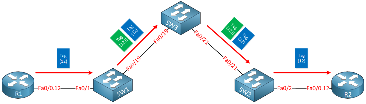
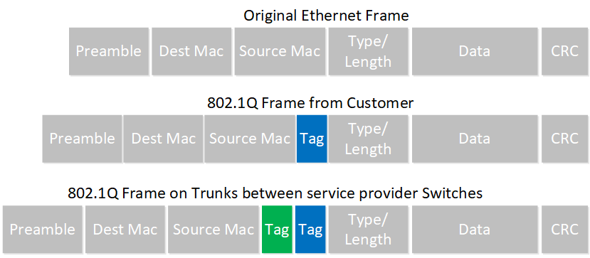
Whenever R1 sends traffic it will tag its frames for VLAN 12. Once it arrives at the service provider, SW1 will add an additional VLAN tag (123). Once SW2 forwards the frame towards R2, it will remove the second VLAN tag and forwards the original tagged frame from R1.
Here is another way to visualize this:
Enough talk…let’s take a look at the configuration.
Here’s what the router configs look like:
R1(config)#interface fastEthernet 0/0
R1(config-if)#no shutdown
R1(config-if)#interface fastEthernet 0/0.12
R1(config-subif)#encapsulation dot1Q 12
R1(config-subif)#ip address 192.168.12.1 255.255.255.0R2(config)#interface fastEthernet 0/0
R2(config-if)#no shutdown
R2(config-if)#interface fastEthernet 0/0.12
R2(config-subif)#encapsulation dot1Q 12
R2(config-subif)#ip address 192.168.12.2 255.255.255.0R1 and R2 are both configured with sub-interfaces and use subnet 192.168.12.0 /24. All their frames are tagged as VLAN 12.
On the service provider network, we’ll have to configure a number of items. First I will configure 802.1Q trunks between SW1 – SW3 and SW2 – SW3:
SW1(config)#interface fastEthernet 0/19
SW1(config-if)#switchport trunk encapsulation dot1q
SW1(config-if)#switchport mode trunkSW2(config)#interface fastEthernet 0/21
SW2(config-if)#switchport trunk encapsulation dot1q
SW2(config-if)#switchport mode trunk SW3(config)#interface fastEthernet 0/19
SW3(config-if)#switchport trunk encapsulation dot1q
SW3(config-if)#switchport mode trunk
SW3(config)#interface fastEthernet 0/21
SW3(config-if)#switchport trunk encapsulation dot1q
SW3(config-if)#switchport mode trunkThe next part is where we configure the actual “Q-in-Q” tunneling. The service provider will use VLAN 123 to transfer everything from our customer. We’ll configure the interfaces toward the customer routers to tag everything for VLAN 123:
SW1(config)#interface fastEthernet 0/1
SW1(config-if)#switchport access vlan 123
SW1(config-if)#switchport mode dot1q-tunnelSW2(config)#interface fastEthernet 0/2
SW2(config-if)#switchport access vlan 123
SW2(config-if)#switchport mode dot1q-tunnelThe switchport mode dot1q-tunnel command tells the switch to tag the traffic and switchport access vlan command is required to specify the Q-in-Q VLAN of 123. Make sure that VLAN 123 is available on SW1, SW2, and SW3. By assigning the interfaces above to this VLAN, it was automatically created on SW1 and SW2, but I also have to make sure that SW3 has VLAN 123 in its database:
SW3(config)#vlan 123Everything is now in place. Let’s do a quick test to see if R1 and R2 can reach each other:
R1#ping 192.168.12.2

Type escape sequence to abort.
Sending 5, 100-byte ICMP Echos to 192.168.12.2, timeout is 2 seconds:
!!!!!
Success rate is 100 percent (5/5), round-trip min/avg/max = 1/2/4 ms
Great! Our ping is working! Let’s take a look at some commands to verify our work:
SW1#show dot1q-tunnel

dot1q-tunnel mode LAN Port(s)
-----------------------------
Fa0/1SW2#show dot1q-tunnel
dot1q-tunnel mode LAN Port(s)
-----------------------------
Fa0/2The show dot1q-tunnel command doesn’t give me a lot of information. The only thing we see are the interfaces that are configured for dot1q tunneling. A good way to prove that the service provider switches are really tunneling the frames from the customer is by looking at the trunks between SW1, SW2, and SW3:
SW1#show interfaces fa0/19 trunk

Port        Mode             Encapsulation  Status        Native vlan
Fa0/19      on               802.1q         trunking      1

Port        Vlans allowed on trunk
Fa0/19      1-4094

Port        Vlans allowed and active in management domain
Fa0/19      1,123

Port        Vlans in spanning tree forwarding state and not pruned
Fa0/19 1,123SW2#show interfaces trunk
Port Mode Encapsulation Status Native vlan
Fa0/21 on 802.1q trunking 1
Port Vlans allowed on trunk
Fa0/21 1-4094
Port Vlans allowed and active in management domain
Fa0/21 1,123
Port Vlans in spanning tree forwarding state and not pruned
Fa0/21 1,123SW3#show interfaces trunk
Port Mode Encapsulation Status Native vlan
Fa1/0/19 on 802.1q trunking 1
Fa1/0/21 auto n-802.1q trunking 1
Port Vlans allowed on trunk
Fa1/0/19 1-4094
Fa1/0/21 1-4094
Port Vlans allowed and active in management domain
Fa1/0/19 1,123
Fa1/0/21 1,123
Port Vlans in spanning tree forwarding state and not pruned
Fa1/0/19 1,123
Fa1/0/21 1,123As you can see above, the only VLAN that is active (besides VLAN 1) on these trunk links is VLAN 123. You won’t see VLAN 12 here because that’s the customer traffic and it’s encapsulated with VLAN 123. Another good way to prove this is by looking at spanning tree:
SW1#show spanning-tree vlan 12

Spanning tree instance(s) for vlan 12 does not exist.SW2#show spanning-tree vlan 12
Spanning tree instance(s) for vlan 12 does not exist.SW3#show spanning-tree vlan 12
Spanning tree instance(s) for vlan 12 does not exist.Our switches don’t have a spanning tree topology for VLAN 12. They don’t care what VLAN the customer is using…they only care about VLAN 123.
So far, so good! 802.1Q tunneling has some more tricks up its sleeve. One of the things it can do is tunnel some layer two protocols. Take a look below:
SW1(config)interface fastEthernet 0/1
SW1(config-if)#l2protocol-tunnel ?
  cdp                 Cisco Discovery Protocol
  drop-threshold      Set drop threshold for protocol packets
  point-to-point      point-to-point L2 Protocol
  shutdown-threshold  Set shutdown threshold for protocol packets
  stp                 Spanning Tree Protocol
  vtp                 Vlan Trunking Protocol
  <cr>
If you want, it can tunnel CDP, VTP, STP, and even point-to-point protocols like PAgP or LACP (Etherchannel). Let me show you what happens when you tunnel CDP traffic:

Great post mate.
First came across this trying to get a CCIE lab set up. Was very useful for that.
Is this still a tech widely used in service providers ?
Thanks Richie,
I haven’t seen it on a real network before and I doubt that it’s still used a lot. A lot of service providers use MPLS which can also transport L2 if you want.
Rene
Great post.
Thanks
Great site…to learn new things…
Thanks for sharing your knowledge…
Take care
You are welcome.