Lesson Contents
PIM sparse mode is a multicast routing protocol that only forwards multicast traffic when requested by receivers. Instead of flooding multicast traffic everywhere like PIM dense mode does. Forwarding multicast traffic only when requested is more efficient than flooding, but it also introduces an issue. Routers with receivers need to figure out where the multicast source is. PIM sparse mode solves this by using a central Rendezvous Point (RP). The RP acts like a central meeting point.
In this lesson, I’ll explain the theory and configuration of PIM Sparse Mode. We’ll cover what the RP does, source registration, how receivers join, and the difference between the Shared Tree (RPT) and the Source Tree (SPT).
Key Takeaways
- PIM sparse mode only forwards multicast traffic when requested.
- The Rendezvous Point (RP) is a central router that acts as a meeting point for sources and receivers.
- Routers send PIM Register messages to inform the RP about multicast sources.
- Receivers join the RPT (Root Path Tree) using PIM Join messages sent toward the RP.
- SPT (Shortest Path Tree) switchover happens automatically when routers learn the source.
Prerequisites
Before starting this lesson, you should have a basic understanding of what multicast is, and you should understand how PIM dense mode works.
Explanation
PIM sparse mode only forwards traffic when requested instead of flooding it everywhere. This introduces one problem…how does a router know where to find the source of multicast traffic? Let me show you a picture to explain this:
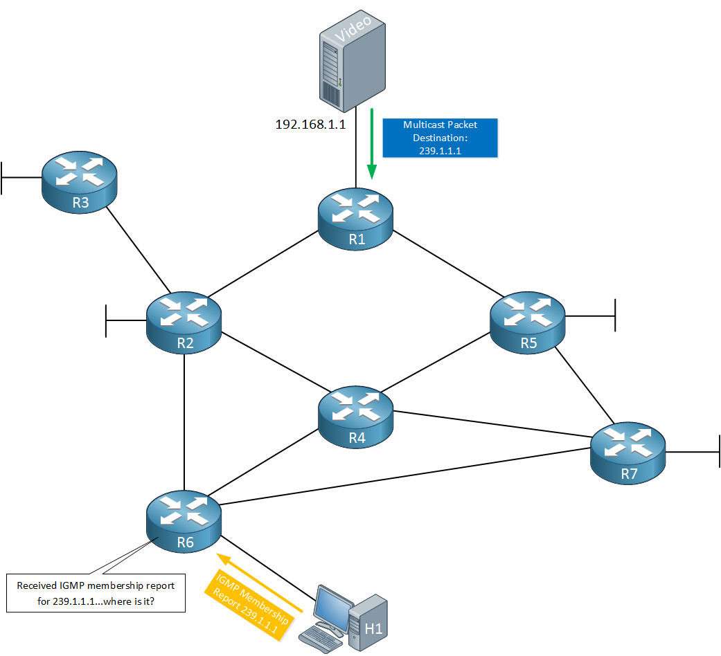
Above we have a video server that is streaming multicast traffic to 239.1.1.1. At the bottom there’s R6 who received an IGMP membership from a directly connected host who would like to receive this multicast traffic.
How is R6 supposed to know that the video server at 192.168.1.1 is sending multicast traffic for this group? With PIM dense mode, this was simple. Multicast traffic was flooded everywhere which allowed R6 to learn the source address.
To solve this issue, PIM sparse mode uses a RP (Rendezvous Point) in the network. Here’s how it works:
- Each router that receives multicast traffic from a source will forward it to the RP.
- Each router that wants to receive multicast traffic will go to the RP.
The RP is like a “meeting point” for multicast traffic. Here’s an example:
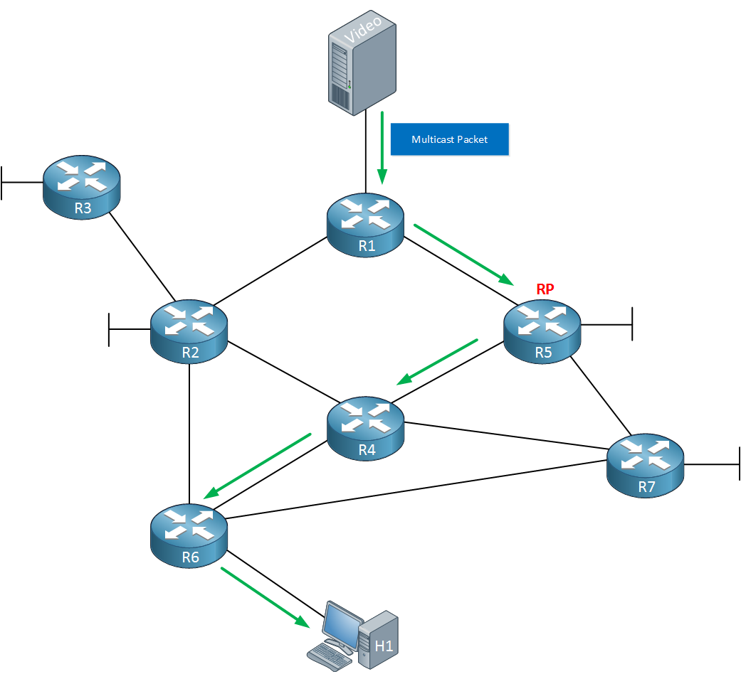
Above you can see that R5 has become the RP in our network. R1 receives multicast traffic from the video server and forwards it to the RP. At the bottom we have R6 that is receiving this multicast traffic from the RP and it is forwarded to the host.
This does introduce another problem though…how does R6 know where to find the RP? There are a couple of different options for this:
- We can manually configure the IP address of the RP on each router.
- There are some protocols that can automatically discover the RP in our network. We’ll talk about this later.
Let’s add some more detail to this story. Let’s imagine that we are using the topology above but at the moment, nobody is interested in the multicast traffic. Here’s what happens:
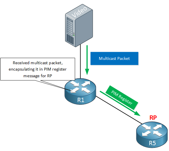
Our video server is forwarding multicast traffic on its interface which is received by R1. Since we are using PIM sparse mode, this router will have to forward the multicast traffic to the RP. Instead of forwarding everything, R1 will only send the first multicast packet. This packet is encapsulated in a PIM register message and forwarded to the RP. Once the RP receives the PIM register message there are two options:
- When nobody is interested in the multicast traffic then the RP will reject the PIM register message.
- When there is at least one receiver, the RP accepts the RP register message.
For now, let’s say that we don’t have any receivers:
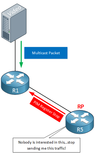
Our RP will respond to R1 with a PIM register stop message. This will inform R1 to stop forwarding any multicast traffic for now. R1 will remain silent for now but not for long:
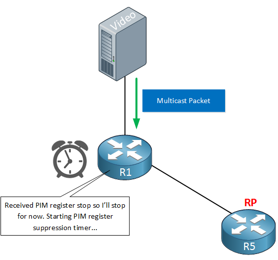
When we receive the PIM register stop packet, R1 will start a suppression timer. By default this timer is 60 seconds and when the timer is almost expired, R1 will send another packet:
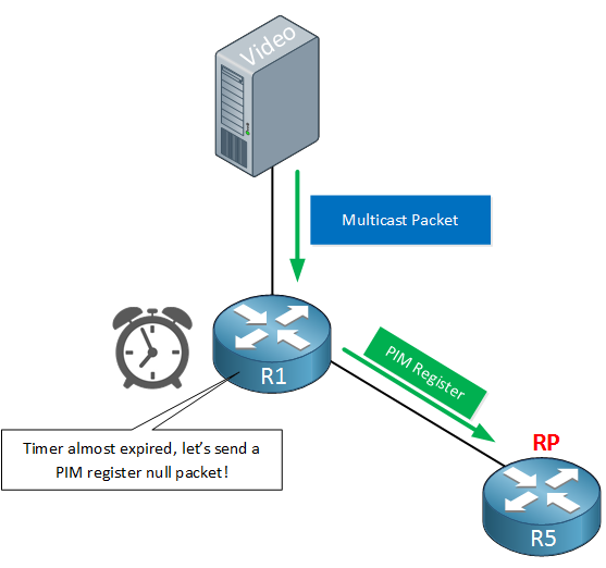
R1 will send another PIM register message but this one doesn’t carry the encapsulated multicast packet. It’s a simple request to ask the RP if it is interested now. This packet is called the PIM register null packet. When we still don’t have any receivers, the RP will send another PIM register stop message. When we do have receivers, the RP will not send a PIM register stop message and R1 will start forwarding the multicast traffic.
Now you know what happens when a source starts sending multicast traffic without any receivers. Let’s see what happens when we do have receivers shall we? Take a look at the picture below:
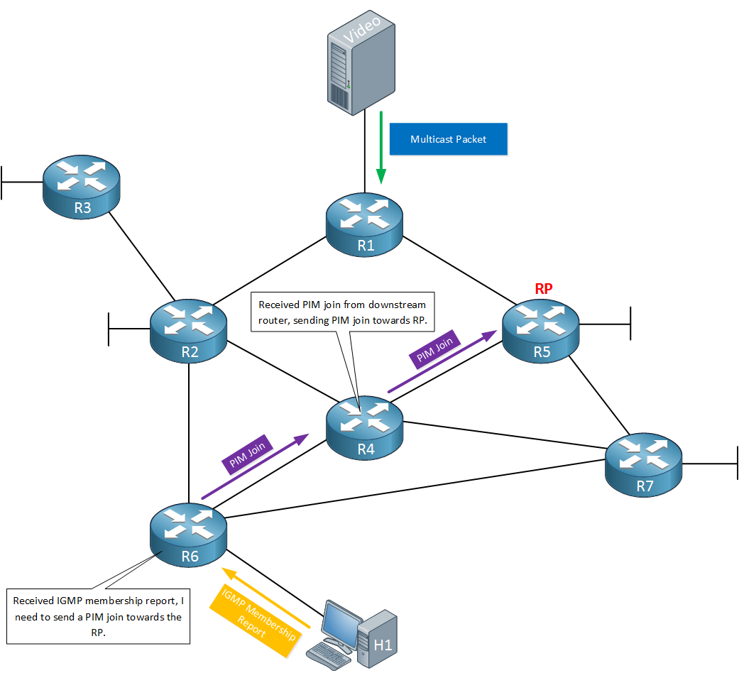
The host that is connected to R6 would like to receive multicast traffic so it sends an IGMP membership report for the multicast group it wants. R6 now has to figure out how to get to the RP and request it to start forwarding the multicast traffic. It will check its unicast routing table for the IP address of the RP and sends a PIM join message on the interface that is used to reach the RP. In this case, that means the PIM join is forwarded towards R4.
When R4 receives the PIM join, it has to request the RP to start forwarding multicast traffic so it will also send a PIM join. It will check its unicast routing table, finds the interface that is used to reach the RP and sends a PIM join message towards the RP.
To summarize this, PIM sparse routers will send a PIM join message when:
- The router has received an IGMP membership report from a host on a directly connected interface.
- The router has received a PIM join from a downstream router.
When the RP receives the PIM join, it will start forwarding the multicast traffic.
This concept of joining the RP is called the RPT (Root Path Tree) or shared distribution tree. The RP is the root of our tree which decides where to forward multicast traffic to. Each multicast group might have different sources and receivers so we might have different RPTs in our network.
The end result will look like this:
Multicast traffic is now flowing from R1 towards the RP, down to R4, R6 and to our receiver (H1).
Are we done now? Not quite…
If you look closely at the picture above then you might have noticed that R6 has multiple paths towards the source. Right now our multicast traffic is flowing like this:
- R1 > R5 > R4 > R6
It’s possible however that this is not the most optimal path. The path from R1 > R2 > R6 has one less router than the current path so if all interfaces are equal, this path is probably better.
Once we are receiving multicast traffic through the RP, it’s possible to switch to the SPT (Source Path Tree).
Here’s what happens next:
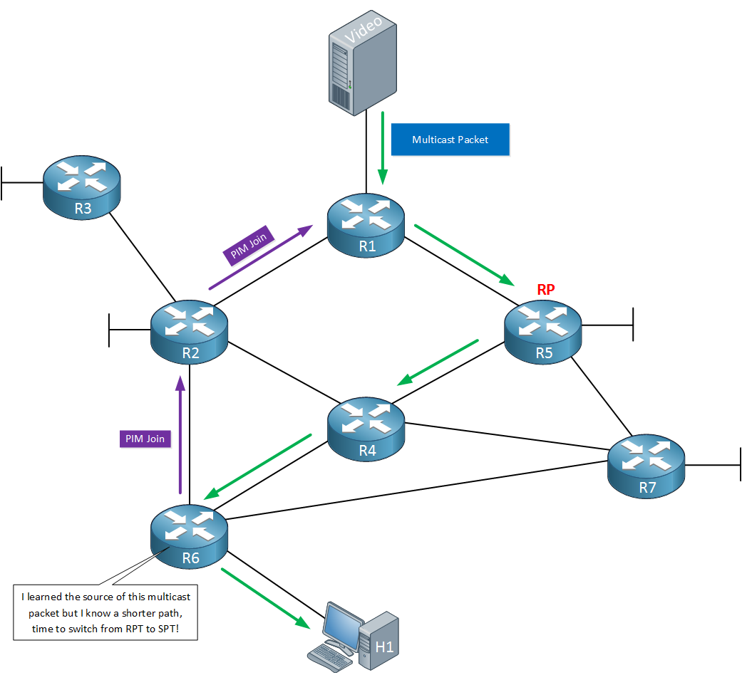
When R6 has received the multicast traffic through the RP, it also learned the source address of this traffic. R6 can now decide it wants to use the SPT instead of the RPT to receive this traffic. When it wants this, it will send PIM join messages towards the source. R1 and R2 will start forwarding multicast traffic towards R6, using the best path:
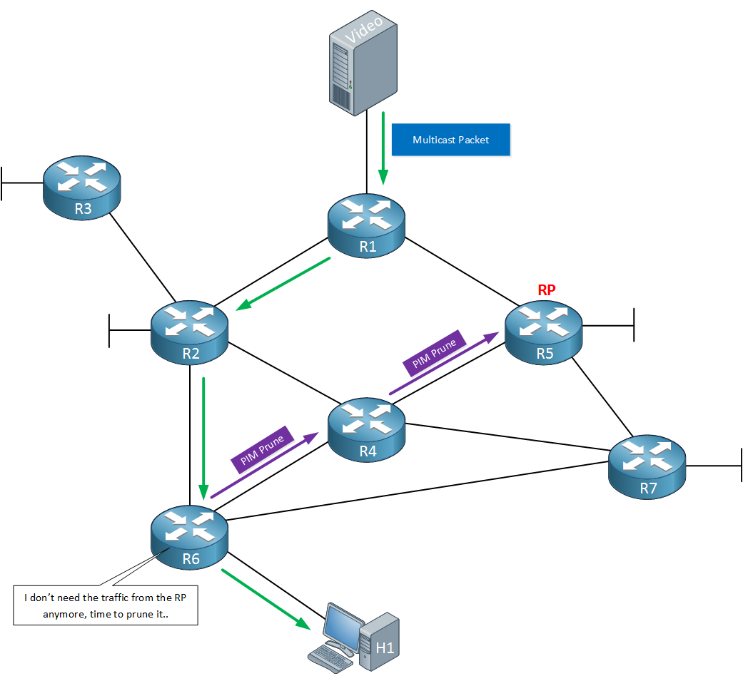
Since R6 is now receiving multicast traffic through R2 and R1, it doesn’t need it from the RP anymore. It will send PIM prune messages towards the RP, informing any routers in between that they can stop forwarding multicast traffic for this group.
You should now have a general idea of how PIM sparse mode works. Let’s configure a small network so you can see this in action!
Configuration
We will use the following topology for this example:
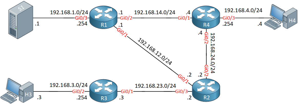
R1, R2, R3 and R4 are our multicast routers that we will configure for PIM sparse mode. S1 will be the source that sends multicast traffic. H3 and H4 are two receivers.
Our routers are running OSPF so that we have full connectivity.
Configurations
Want to follow me with this example? Here you will find the startup configuration of each device.
H3
hostname H3
!
interface GigabitEthernet0/1
 ip address 192.168.3.3 255.255.255.0
 no ip route-cache
 duplex auto
 speed auto
 media-type rj45
!
ip default-gateway 192.168.3.254
!
end
H4
hostname H4
!
interface GigabitEthernet0/1
 ip address 192.168.4.4 255.255.255.0
 no ip route-cache
 duplex auto
 speed auto
 media-type rj45
!
ip default-gateway 192.168.4.254
!
end
R1
hostname R1
!
interface GigabitEthernet0/1
 ip address 192.168.12.1 255.255.255.0
 duplex auto
 speed auto
 media-type rj45
!
interface GigabitEthernet0/2
 ip address 192.168.14.1 255.255.255.0
 duplex auto
 speed auto
 media-type rj45
!
interface GigabitEthernet0/3
 ip address 192.168.1.254 255.255.255.0
 duplex auto
 speed auto
 media-type rj45
!
router ospf 1
 network 192.168.1.0 0.0.0.255 area 0
 network 192.168.12.0 0.0.0.255 area 0
 network 192.168.14.0 0.0.0.255 area 0
!
end
R2
hostname R2
!
interface GigabitEthernet0/1
 ip address 192.168.12.2 255.255.255.0
 duplex auto
 speed auto
 media-type rj45
!
interface GigabitEthernet0/2
 ip address 192.168.24.2 255.255.255.0
 duplex auto
 speed auto
 media-type rj45
!
interface GigabitEthernet0/3
 ip address 192.168.23.2 255.255.255.0
 duplex auto
 speed auto
 media-type rj45
!
router ospf 1
 network 192.168.12.0 0.0.0.255 area 0
 network 192.168.23.0 0.0.0.255 area 0
 network 192.168.24.0 0.0.0.255 area 0
!
end
R3
hostname R3
!
interface GigabitEthernet0/1
 ip address 192.168.23.3 255.255.255.0
 duplex auto
 speed auto
 media-type rj45
!
interface GigabitEthernet0/2
 ip address 192.168.3.254 255.255.255.0
 duplex auto
 speed auto
 media-type rj45
!
router ospf 1
 network 192.168.3.0 0.0.0.255 area 0
 network 192.168.23.0 0.0.0.255 area 0
!
end
R4
hostname R4
!
interface GigabitEthernet0/1
 ip address 192.168.14.4 255.255.255.0
 duplex auto
 speed auto
 media-type rj45
!
interface GigabitEthernet0/2
 ip address 192.168.24.4 255.255.255.0
 duplex auto
 speed auto
 media-type rj45
!
interface GigabitEthernet0/3
 ip address 192.168.4.254 255.255.255.0
 duplex auto
 speed auto
 media-type rj45
!
router ospf 1
 network 192.168.4.0 0.0.0.255 area 0
 network 192.168.14.0 0.0.0.255 area 0
 network 192.168.24.0 0.0.0.255 area 0
!
end
S1
hostname S1
!
interface GigabitEthernet0/1
 ip address 192.168.1.1 255.255.255.0
 no ip route-cache
 duplex auto
 speed auto
 media-type rj45
!
ip default-gateway 192.168.1.254
!
end
Now we can focus on the multicast configuration.
PIM Sparse Mode
Multicast routing is disabled by default on Cisco IOS routers so we have to enable it:
R1, R2, R3 & R4
(config)#ip multicast-routing
Now we can configure PIM. Let’s start with R1:
R1(config)#interface GigabitEthernet 0/1
R1(config-if)#ip pim sparse-mode
As soon as I enable PIM sparse mode on the interface, our router will start sending PIM hello packets. Here’s what these look like in wireshark:
Frame 1: 72 bytes on wire (576 bits), 72 bytes captured (576 bits) on interface 0
Ethernet II, Src: fa:16:3e:97:ad:ec (fa:16:3e:97:ad:ec), Dst: IPv4mcast_0d (01:00:5e:00:00:0d)
Internet Protocol Version 4, Src: 192.168.12.1, Dst: 224.0.0.13
Protocol Independent Multicast
    0010 .... = Version: 2
    .... 0000 = Type: Hello (0)
    Reserved byte(s): 00
    Checksum: 0xb680 [correct]
    PIM Options: 5
        Option 1: Hold Time
            Holdtime: 1
        Option 20: Generation ID: 2454558607
            Type: 20
            Length: 4
            Generation ID: 2454558607
        Option 19: DR Priority: 1
            Type: 19
            Length: 4
            DR Priority: 1
        Option 21: State Refresh Capable: Version = 1, Interval = 0s
            Type: 21
            Length: 4
            Version: 1
            Interval: 0
            Reserved: 0
        Option 65004: Unknown: 65004
            Type: 65004
            Length: 0
Above you can see the type of the packet (hello) and it also shows the hold time. For whatever reason, wireshark (version 2.0.1) is showing me a value of 1 but the default is 105 seconds. If you want to take a look at this packet yourself, here’s the capture file if you want to take a look:
Packet Capture: Multicast PIM Sparse Mode Hello Packet
It shows the correct holdtime of 105 seconds.
Let’s enable PIM sparse mode on R2 as well:
R2(config)#interface GigabitEthernet 0/1
R2(config-if)#ip pim sparse-mode
As soon as we do this, R1 and R2 will become neighbors since they receive each others PIM hello packets.If they keep receiving them before the holddown timer is expired then they will keep seeing each other as PIM neighbors.:
R1#
%PIM-5-NBRCHG: neighbor 192.168.12.2 UP on interface GigabitEthernet0/1
Let’s enable all the other interfaces. You need to enable PIM on all interfaces that will send or receive multicast traffic. Including the interfaces that connects to sources and receivers:
R1(config)#interface GigabitEthernet 0/2
R1(config-if)#ip pim sparse-mode

R1(config)#interface GigabitEthernet 0/3
R1(config-if)#ip pim sparse-modeR2(config)#interface GigabitEthernet 0/2
R2(config-if)#ip pim sparse-mode
R2(config)#interface GigabitEthernet 0/3
R2(config-if)#ip pim sparse-modeR3(config)#interface GigabitEthernet 0/1
R3(config-if)#ip pim sparse-mode
R3(config)#interface GigabitEthernet 0/2
R3(config-if)#ip pim sparse-mode R4(config)#interface GigabitEthernet 0/1
R4(config-if)#ip pim sparse-mode
R4(config)#interface GigabitEthernet 0/2
R4(config-if)#ip pim sparse-mode
R4(config)#interface GigabitEthernet 0/3
R4(config-if)#ip pim sparse-mode That takes care of the interfaces…
PIM Sparse Neighbors
Let’s make sure all routers have become neighbors:
R1#show ip pim neighbor
PIM Neighbor Table
Mode: B - Bidir Capable, DR - Designated Router, N - Default DR Priority,
      P - Proxy Capable, S - State Refresh Capable, G - GenID Capable,
      L - DR Load-balancing Capable
Neighbor          Interface                Uptime/Expires    Ver   DR
Address                                                            Prio/Mode
192.168.12.2      GigabitEthernet0/1       00:00:17/00:01:27 v2    1 / DR S P G
192.168.14.4 GigabitEthernet0/2 00:00:15/00:01:29 v2 1 / DR S P GR2#show ip pim neighbor
PIM Neighbor Table
Mode: B - Bidir Capable, DR - Designated Router, N - Default DR Priority,
P - Proxy Capable, S - State Refresh Capable, G - GenID Capable,
L - DR Load-balancing Capable
Neighbor Interface Uptime/Expires Ver DR
Address Prio/Mode
192.168.12.1 GigabitEthernet0/1 00:00:40/00:01:36 v2 1 / S P G
192.168.24.4 GigabitEthernet0/2 00:00:38/00:01:35 v2 1 / DR S P G
192.168.23.3 GigabitEthernet0/3 00:00:37/00:01:36 v2 1 / DR S P GR3#show ip pim neighbor
PIM Neighbor Table
Mode: B - Bidir Capable, DR - Designated Router, N - Default DR Priority,
P - Proxy Capable, S - State Refresh Capable, G - GenID Capable,
L - DR Load-balancing Capable
Neighbor Interface Uptime/Expires Ver DR
Address Prio/Mode
192.168.23.2 GigabitEthernet0/1 00:00:55/00:01:22 v2 1 / S P GR4#show ip pim neighbor
PIM Neighbor Table
Mode: B - Bidir Capable, DR - Designated Router, N - Default DR Priority,
P - Proxy Capable, S - State Refresh Capable, G - GenID Capable,
L - DR Load-balancing Capable
Neighbor Interface Uptime/Expires Ver DR
Address Prio/Mode
192.168.14.1 GigabitEthernet0/1 00:01:11/00:01:33 v2 1 / S P G
192.168.24.2 GigabitEthernet0/2 00:01:11/00:01:35 v2 1 / S P GAbove we can see that all routers have become PIM neighbors. The default version on Cisco IOS is PIM version 2. The expiry time is the holddown timer that is counting down. Each time when the router receives a PIM hello packet, it will reset itself to 00:01:45 (105 seconds).
Multicast Routing
Nothing is going on at the moment, let’s see if there is anything in the multicast routing tables:
R1#show ip mroute
IP Multicast Routing Table
Flags: D - Dense, S - Sparse, B - Bidir Group, s - SSM Group, C - Connected,
       L - Local, P - Pruned, R - RP-bit set, F - Register flag,
       T - SPT-bit set, J - Join SPT, M - MSDP created entry, E - Extranet,
       X - Proxy Join Timer Running, A - Candidate for MSDP Advertisement,
       U - URD, I - Received Source Specific Host Report,
       Z - Multicast Tunnel, z - MDT-data group sender,
       Y - Joined MDT-data group, y - Sending to MDT-data group,
       G - Received BGP C-Mroute, g - Sent BGP C-Mroute,
       N - Received BGP Shared-Tree Prune, n - BGP C-Mroute suppressed,
       Q - Received BGP S-A Route, q - Sent BGP S-A Route,
       V - RD & Vector, v - Vector, p - PIM Joins on route,
       x - VxLAN group
Outgoing interface flags: H - Hardware switched, A - Assert winner, p - PIM Join
 Timers: Uptime/Expires
 Interface state: Interface, Next-Hop or VCD, State/Mode

(*, 224.0.1.40), 00:01:35/00:02:29, RP 0.0.0.0, flags: DCL
  Incoming interface: Null, RPF nbr 0.0.0.0
  Outgoing interface list:
    GigabitEthernet0/2, Forward/Sparse, 00:01:34/00:01:25
    GigabitEthernet0/1, Forward/Sparse, 00:01:35/00:01:23
Above we see the output of R1. At this moment we are not transmitting/receiving any multicast traffic but we still see something in the multicast routing tables. There’s an entry for 224.0.1.40. This multicast group address is used for Auto RP discovery, a protocol that dynamically learns RPs on the network.
The multicast routing table shows a lot of different flags, we’ll discuss some of them in this lesson. To save some virtual real estate pixel space I won’t show them over and over again when we look at the multicast routing tables.
The other router multicast routing tables are similar:
R2#show ip mroute

(*, 224.0.1.40), 00:02:00/00:02:10, RP 0.0.0.0, flags: DCL
  Incoming interface: Null, RPF nbr 0.0.0.0
  Outgoing interface list:
GigabitEthernet0/1, Forward/Sparse, 00:02:00/00:01:59R3#show ip mroute
(*, 224.0.1.40), 00:02:16/00:02:47, RP 0.0.0.0, flags: DCL
Incoming interface: Null, RPF nbr 0.0.0.0
Outgoing interface list:
GigabitEthernet0/1, Forward/Sparse, 00:02:16/00:02:47R4#show ip mroute
(*, 224.0.1.40), 00:02:36/00:02:35, RP 0.0.0.0, flags: DCL
Incoming interface: Null, RPF nbr 0.0.0.0
Outgoing interface list:
GigabitEthernet0/1, Forward/Sparse, 00:02:36/00:02:35When you are studying multicast it can be annoying to see the autoRP group address, especially in debug messages. Since IOS version 15.0(1)M it’s finally possible to disable auto RP. We don’t need it in this lesson so let’s disable it:
R1, R2, R3 & R4
(config)#no ip pim autorp
Rendezvous Point
In this lesson we are going to keep it simple, instead of learning the RP dynamically we are going to configure it manually. Right now we don’t have a RP so it’s time configure one. R2 will be our RP and we’ll use one of its IP addresses as the RP address. Physical interfaces can go down so it’s better to use a loopback interface for the RP address:
Great Lesson!!!
Hi Renee,
Excellent article!
One point to emphasize is that PIM packets travel to and from a pingable address, so with multicast fault-fining, if you cannot ping the RP, multicast source or host, muticast won’t work.
Cheers,
Hans
Great Post Rene!!
I have a question, If I have the RP in the router do I need to configure the RP also in the switch since this is multilayer?
-Daniel
Hi Daniel,
You might, depending on your network design. If your multilayer switch has to route multicast traffic from one VLAN to another then you will need PIM yes.
If it only has to deliver multicast traffic within the VLAN, then IGMP snooping is all you need.
Rene
Hi Renee,
How does bidir-PIM relate to PiM-sparse, it seems that bidir-PIM has some advantages?
Best regards,
Hans de Roode.