Lesson Contents
In a Cisco SD-WAN network, vEdge routers build a full-mesh topology with vEdge routers in other sites. This is the default behavior, and it means that all devices within a service VPN can communicate with each other. However, a full mesh topology is not always required, and with many vEdge routers, it can even become a scalability issue.
This lesson will explain how you can use a centralized policy to configure a hub and spoke topology. The hub site will be able to communicate with all spoke sites. However, spoke sites can only communicate with the hub and not with other spoke sites.
This is the topology we’ll use:
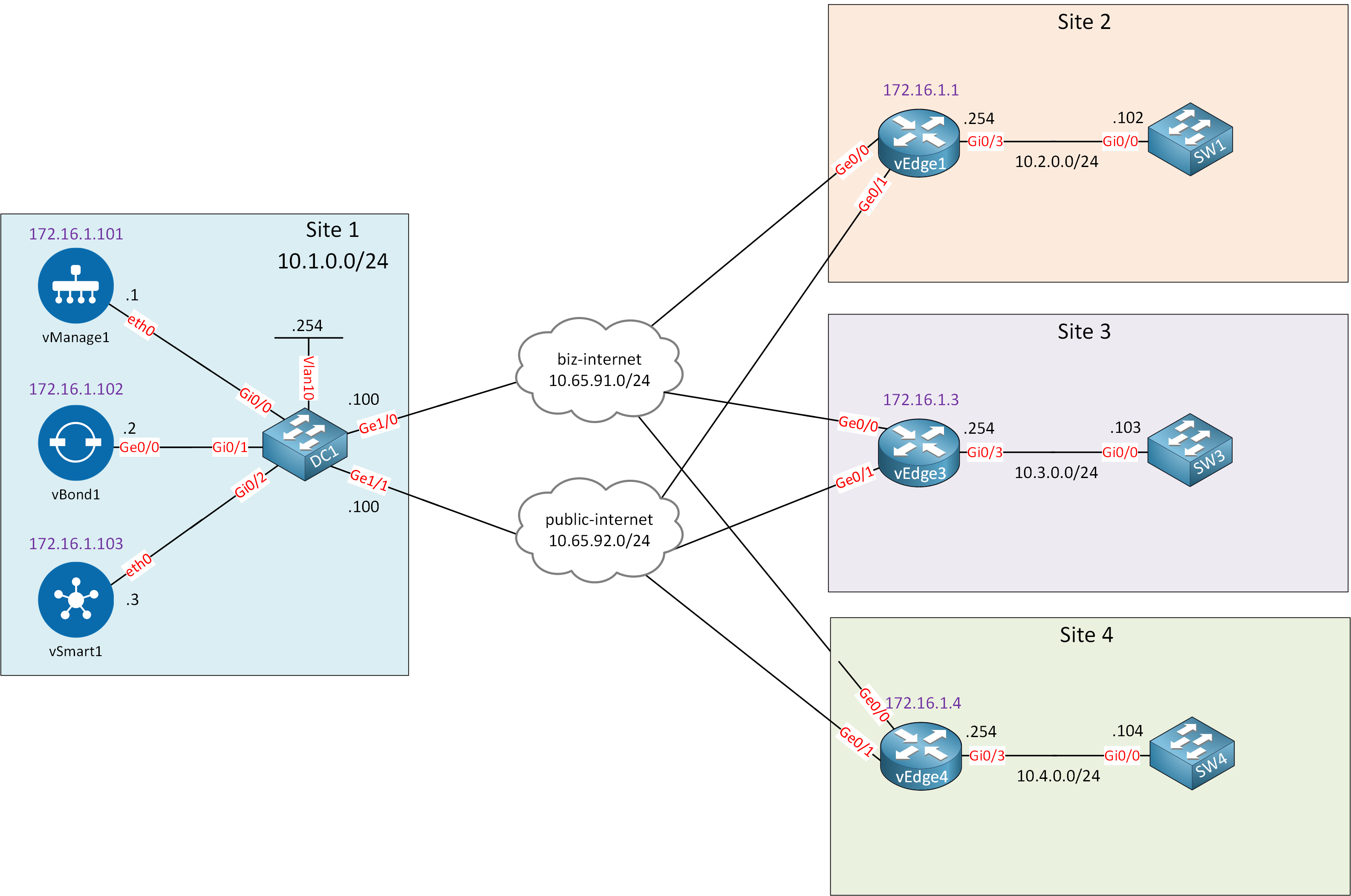
We have three sites, and I assigned the Gi0/3 interfaces of all vEdge routers to service VPN 10. We’ll do a “before and after” scenario so you can see the difference between the default (full mesh) and a hub and spoke topology. I am using Cisco SD-WAN version 19.3.0.
Configurations
Want to take a look for yourself? Here you will find the startup configuration of each device.
vEdge1
system
 host-name               vEdge1
 system-ip               172.16.1.1
 site-id                 2
 organization-name       nwl-lab-sdwan
 vbond 10.1.0.2
!
omp
 no shutdown
 graceful-restart
 advertise connected
 advertise static
!
banner
 motd "Welcome to the vEdge router!"
!
vpn 0
 interface ge0/0
  ip address 10.65.91.1/24
  tunnel-interface
   encapsulation ipsec
   color biz-internet
   allow-service all
  !
  no shutdown
 !
 interface ge0/1
  ip address 10.65.92.1/24
  tunnel-interface
   encapsulation ipsec
   color public-internet
   allow-service all
  !
  no shutdown
 !
 ip route 10.1.0.0/24 10.65.91.100
 ip route 10.1.0.0/24 10.65.92.100
!
vpn 10
 interface ge0/3
  ip address 10.2.0.254/24
  no shutdown
 !
 omp
  advertise connected
 !
!
vpn 512
 interface eth0
  shutdown
 !
!
vEdge3
system
 host-name               vEdge3
 system-ip               172.16.1.3
 site-id                 3
 organization-name       nwl-lab-sdwan
 vbond 10.1.0.2
!
omp
 no shutdown
 graceful-restart
 advertise connected
 advertise static
!
banner
 motd "Welcome to the vEdge router!"
!
vpn 0
 interface ge0/0
  ip address 10.65.91.3/24
  tunnel-interface
   encapsulation ipsec
   color biz-internet
   allow-service all
  !
  no shutdown
 !
 interface ge0/1
  ip address 10.65.92.3/24
  tunnel-interface
   encapsulation ipsec
   color public-internet
   allow-service all
  !
  no shutdown
 !
 ip route 10.1.0.0/24 10.65.91.100
 ip route 10.1.0.0/24 10.65.92.100
!
vpn 10
 interface ge0/3
  ip address 10.3.0.254/24
  no shutdown
 !
 omp
  advertise connected
 !
!
vpn 512
 interface eth0
  shutdown
 !
!
vEdge4
system
 host-name               vEdge4
 system-ip               172.16.1.4
 site-id                 4
 organization-name       nwl-lab-sdwan
 vbond 10.1.0.2
!
omp
 no shutdown
 graceful-restart
 advertise connected
 advertise static
!
banner
 motd "Welcome to the vEdge router!"
!
vpn 0
 interface ge0/0
  ip address 10.65.91.4/24
  tunnel-interface
   encapsulation ipsec
   color biz-internet
   allow-service all
  !
  no shutdown
 !
 interface ge0/1
  ip address 10.65.92.4/24
  tunnel-interface
   encapsulation ipsec
   color public-internet
   allow-service all
  !
  no shutdown
 !
 ip route 10.1.0.0/24 10.65.91.100
 ip route 10.1.0.0/24 10.65.92.100
!
vpn 10
 interface ge0/3
  ip address 10.4.0.254/24
  no shutdown
 !
 omp
  advertise connected
 !
!
vpn 512
 interface eth0
  shutdown
 !
!
SW1
hostname SW1
!
no ip routing
!
interface GigabitEthernet0/0
 no switchport
 ip address 10.2.0.101 255.255.255.0
!
ip default-gateway 10.2.0.254
!
end
SW3
hostname SW3
!
no ip routing
!
interface GigabitEthernet0/0
 no switchport
 ip address 10.3.0.103 255.255.255.0
!
ip default-gateway 10.3.0.254
!
end
SW4
hostname SW3
!
no ip routing
!
interface GigabitEthernet0/0
 no switchport
 ip address 10.4.0.104 255.255.255.0
!
ip default-gateway 10.4.0.254
!
end
Full Mesh Topology
The default is a full mesh topology. This means that all sites can reach each other. So, for example, I can ping from SW3 to both SW1 and SW4:
SW3#ping 10.2.0.101
Type escape sequence to abort.
Sending 5, 100-byte ICMP Echos to 10.2.0.101, timeout is 2 seconds:
!!!!!
Success rate is 100 percent (5/5), round-trip min/avg/max = 51/63/79 msSW3#ping 10.4.0.104
Type escape sequence to abort.
Sending 5, 100-byte ICMP Echos to 10.4.0.104, timeout is 2 seconds:
!!!!!
Success rate is 100 percent (5/5), round-trip min/avg/max = 52/65/74 msSW4 can also ping SW1:
SW4#ping 10.2.0.101
Type escape sequence to abort.
Sending 5, 100-byte ICMP Echos to 10.2.0.101, timeout is 2 seconds:
!!!!!
Success rate is 100 percent (5/5), round-trip min/avg/max = 55/63/72 ms
We have full connectivity because each vEdge router advertises its prefix through OMP to the vSmart controller. The vSmart controller advertises all prefixes to the vEdge routers.
show ip routes omp and show ipsec outputs below, I removed non-relevant columns to keep it readable.You can see the OMP routes below:
vEdge1# show ip routes omp | begin VPN
VPN    PREFIX              PROTOCOL     TLOC IP          COLOR            ENCAP  STATUS
---------------------------------------------------------------------------------------
10     10.3.0.0/24         omp          172.16.1.3       biz-internet     ipsec  F,S
10     10.3.0.0/24         omp          172.16.1.3       public-internet  ipsec  F,S
10     10.4.0.0/24         omp          172.16.1.4       biz-internet     ipsec  F,S
10     10.4.0.0/24         omp          172.16.1.4       public-internet  ipsec  F,S
vEdge3# show ip routes omp | begin VPN
VPN PREFIX PROTOCOL TLOC IP COLOR ENCAP STATUS
---------------------------------------------------------------------------------------
10 10.2.0.0/24 omp 172.16.1.1 biz-internet ipsec F,S
10 10.2.0.0/24 omp 172.16.1.1 public-internet ipsec F,S
10 10.4.0.0/24 omp 172.16.1.4 biz-internet ipsec F,S
10 10.4.0.0/24 omp 172.16.1.4 public-internet ipsec F,SvEdge4# show ip routes omp | begin VPN
VPN PREFIX PROTOCOL TLOC IP COLOR ENCAP STATUS
----------------------------------------------------------------------------------------
10 10.2.0.0/24 omp 172.16.1.1 biz-internet ipsec F,S
10 10.2.0.0/24 omp 172.16.1.1 public-internet ipsec F,S
10 10.3.0.0/24 omp 172.16.1.3 biz-internet ipsec F,S
10 10.3.0.0/24 omp 172.16.1.3 public-internet ipsec F,SIn the output above, you can see that all prefixes are learned and installed. One for each WAN connection.
This also means that all vEdge routers establish IPSec connections with each other. Between TLOCs on one WAN interface and TLOCs of different WAN interfaces (if there is reachability between the two WAN clouds). That is the case with two Internet connections like I have, but not if you have a private WAN connection (like MPLS). You can see the IPSec connections below:
vEdge1# show ipsec outbound-connections
SOURCE       SOURCE  DEST         DEST                  REMOTE         REMOTE
IP           PORT    IP           PORT    SPI  TUN MTU  TLOC ADDRESS   TLOC COLOR
-------------------------------------------------------------------------------------
10.65.91.1   12346   10.65.91.3   12346   259  1441    172.16.1.3      biz-internet
10.65.91.1   12346   10.65.91.4   12346   256  1441    172.16.1.4      biz-internet
10.65.91.1   12346   10.65.92.3   12346   259  1442    172.16.1.3      public-internet
10.65.91.1   12346   10.65.92.4   12346   256  1442    172.16.1.4      public-internet
10.65.92.1   12346   10.65.91.3   12346   259  1442    172.16.1.3      biz-internet
10.65.92.1   12346   10.65.91.4   12346   256  1442    172.16.1.4      biz-internet
10.65.92.1   12346   10.65.92.3   12346   259  1441    172.16.1.3      public-internet
10.65.92.1   12346   10.65.92.4   12346   256  1441    172.16.1.4      public-internet
vEdge3# show ipsec outbound-connections
SOURCE SOURCE DEST DEST REMOTE REMOTE
IP PORT IP PORT SPI TUN MTU TLOC ADDRESS TLOC COLOR
--------------------------------------------------------------------------------------
10.65.91.3 12346 10.65.91.1 12346 257 1441 172.16.1.1 biz-internet
10.65.91.3 12346 10.65.91.4 12346 256 1441 172.16.1.4 biz-internet
10.65.91.3 12346 10.65.92.1 12346 257 1442 172.16.1.1 public-internet
10.65.91.3 12346 10.65.92.4 12346 256 1442 172.16.1.4 public-internet
10.65.92.3 12346 10.65.91.1 12346 257 1442 172.16.1.1 biz-internet
10.65.92.3 12346 10.65.91.4 12346 256 1442 172.16.1.4 biz-internet
10.65.92.3 12346 10.65.92.1 12346 257 1441 172.16.1.1 public-internet
10.65.92.3 12346 10.65.92.4 12346 256 1441 172.16.1.4 public-internetvEdge4# show ipsec outbound-connections
SOURCE SOURCE DEST DEST REMOTE REMOTE
IP PORT IP PORT SPI TUN MTU TLOC ADDRESS TLOC COLOR
----------------------------------------------------------------------------------
10.65.91.4 12346 10.65.91.1 12346 257 1441 172.16.1.1 biz-internet
10.65.91.4 12346 10.65.91.3 12346 259 1441 172.16.1.3 biz-internet
10.65.91.4 12346 10.65.92.1 12346 257 1442 172.16.1.1 public-internet
10.65.91.4 12346 10.65.92.3 12346 259 1442 172.16.1.3 public-internet
10.65.92.4 12346 10.65.91.1 12346 257 1442 172.16.1.1 biz-internet
10.65.92.4 12346 10.65.91.3 12346 259 1442 172.16.1.3 biz-internet
10.65.92.4 12346 10.65.92.1 12346 257 1441 172.16.1.1 public-internet
10.65.92.4 12346 10.65.92.3 12346 259 1441 172.16.1.3 public-internetEach vEdge router has 8 IPSec connections, and we only have three routers (with two WAN interfaces). This can become a scalability issue with large topologies, especially if you have low-end branch vEdge routers.
Configuration
Let’s change our topology from full mesh to a hub and spoke topology.
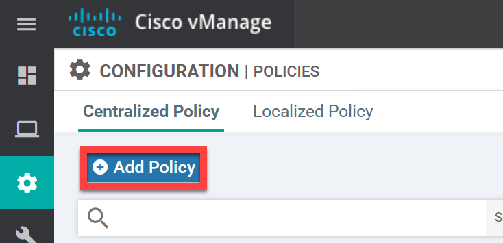
Centralized Policy
Go to Configuration > Policies > Centralized Policy and click on Add Policy:
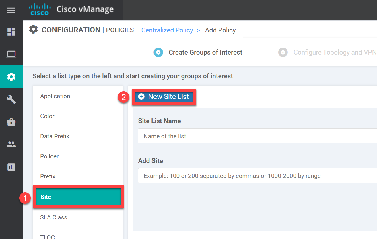
Groups of Interest
We need to create two items:
- Site List: A list so we know which site will be the hub and which sites will be the spokes.
- VPN List: The VPN that we want to create a hub and spoke topology for.
Site List
Under Groups of Interest, add a New Site List:
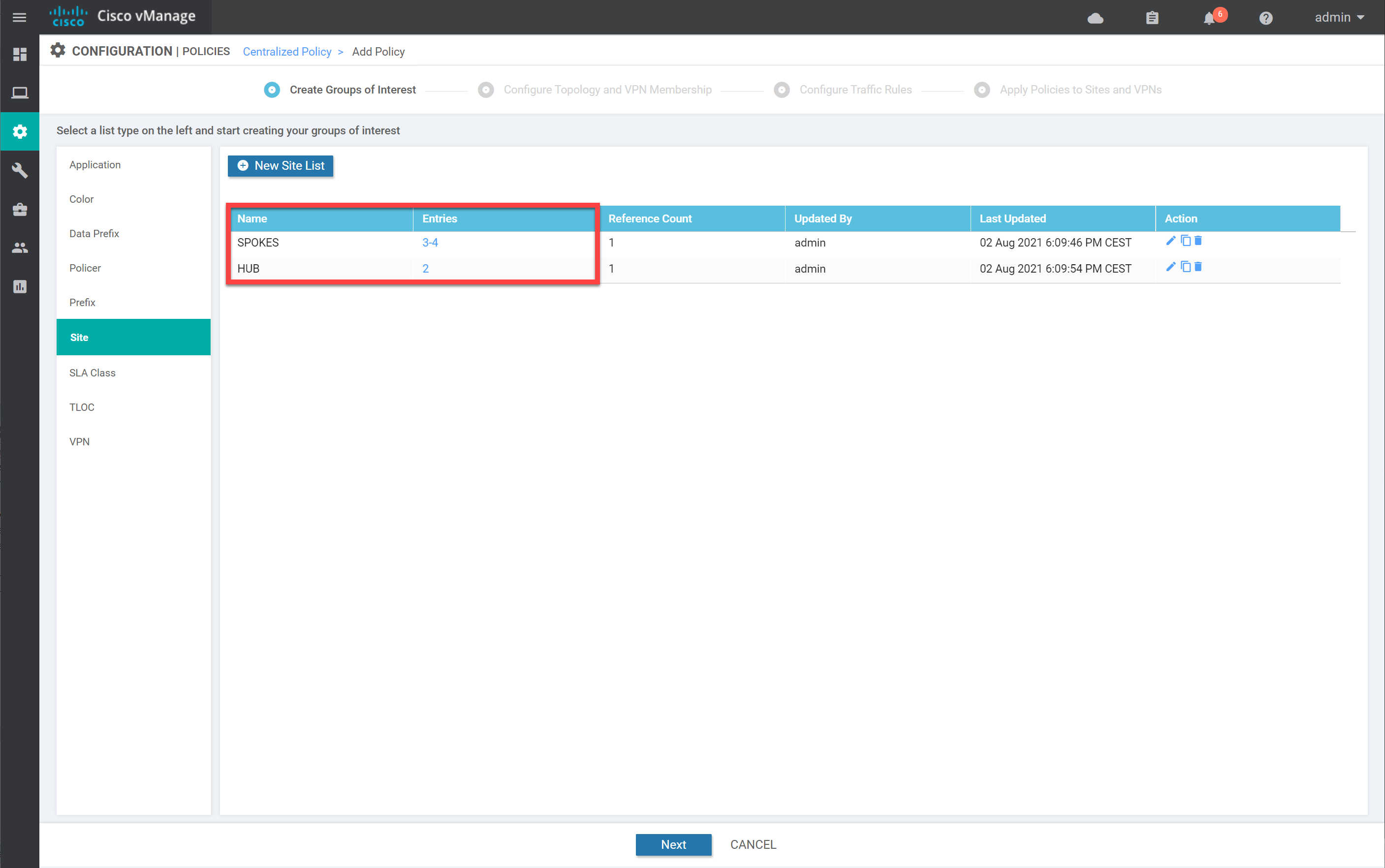
We create two lists here:
- HUB: site 2.
- SPOKES: site 3 and 4.
Create the lists, so your overview looks like this:
VPN
Let’s create the VPN list. Under Groups of Interest, select VPN. Enter a name and the VPN number (10) here:
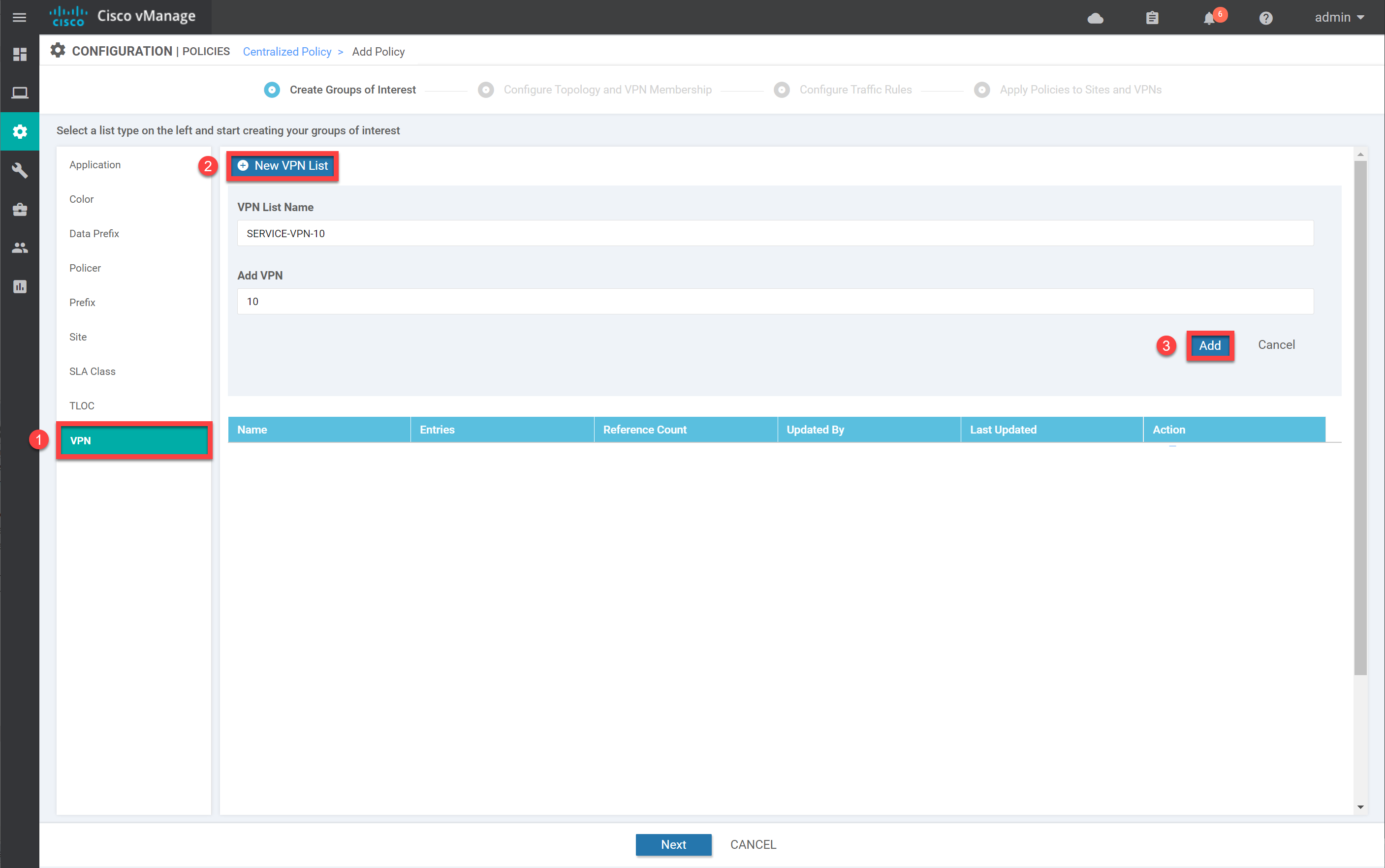
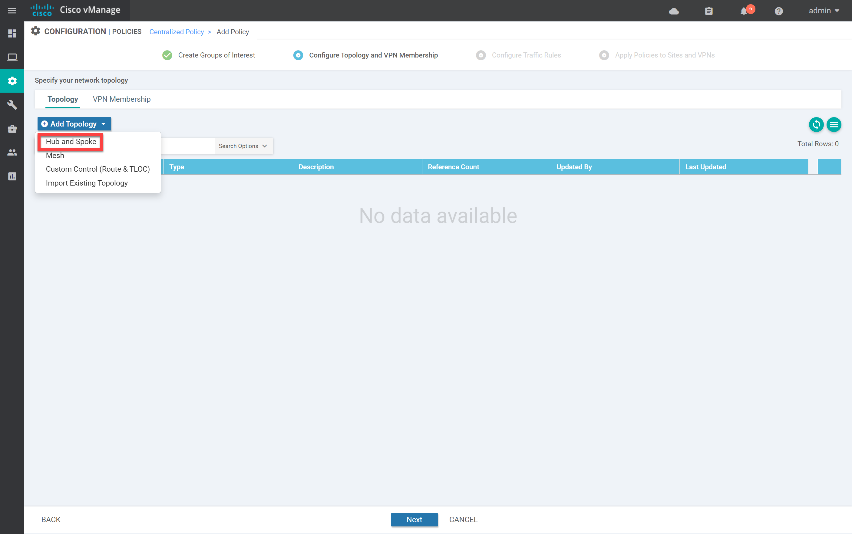
Click on Add to continue. Then, under Topology, click on Add Topology and select Hub-and-Spoke:
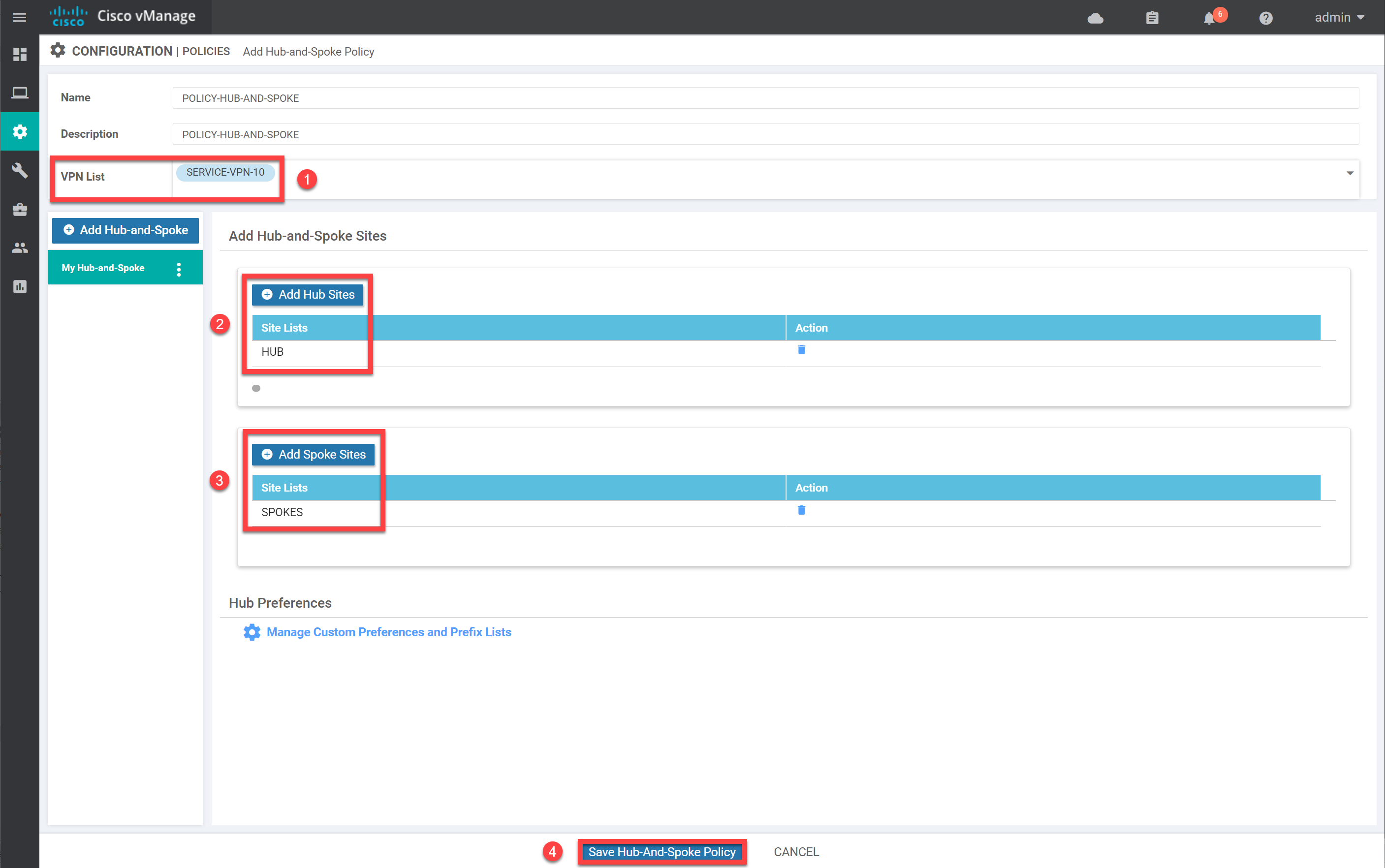
Give the policy a name, select the VPN List we created, and select the Hub and Spoke Sites. Click on Save Hub-And-Spoke Policy to save the policy:
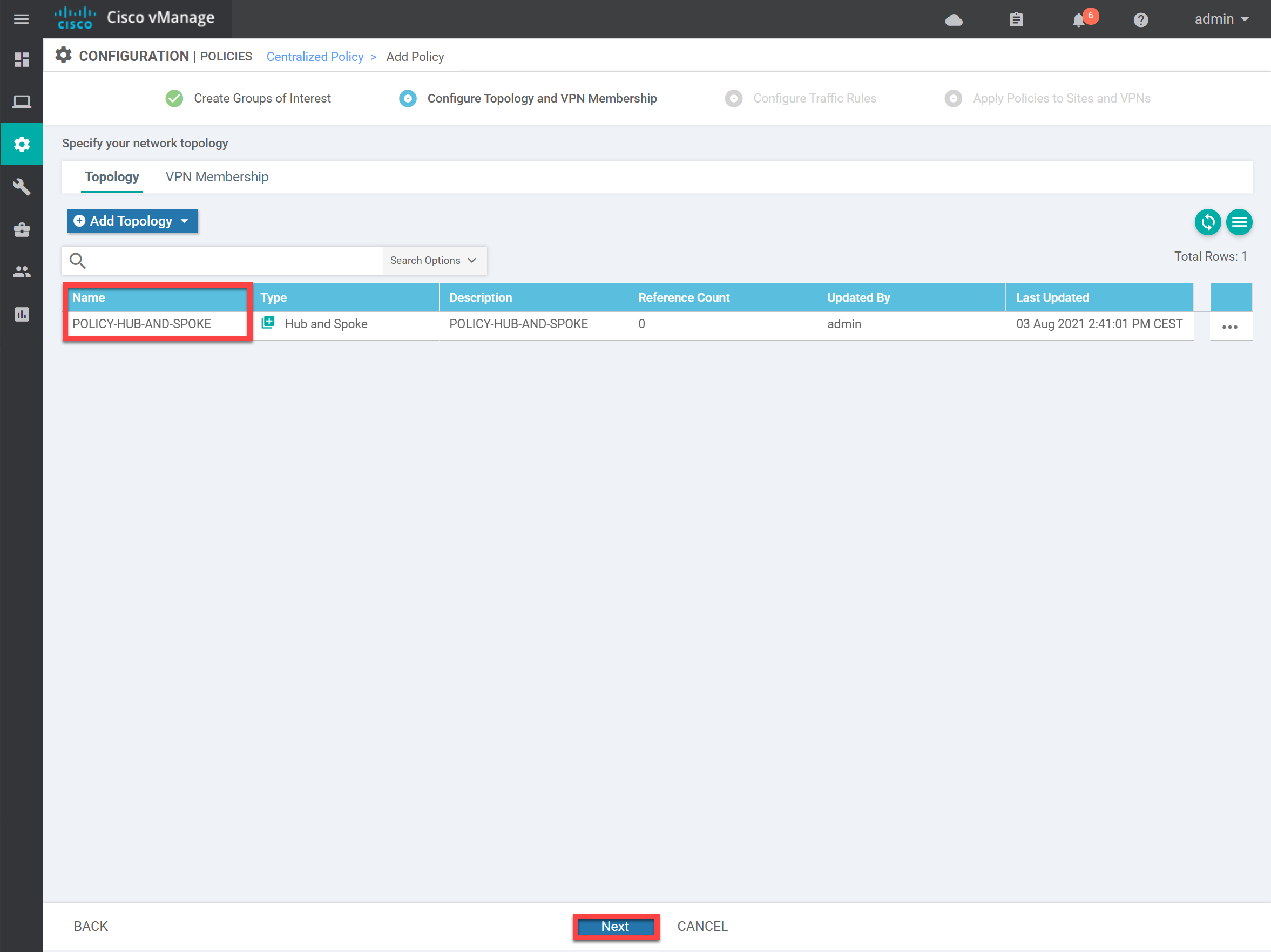
The policy now shows up in the overview. Click on Next:
We don’t need any Traffic Rules, so click on Next:
Hi Rene,
Thanks for your video. What if I want a hub and spoke topology, but I still want a communication between the Spokes (Through the HUB).
In this example we see that the communications between spokes is now impossible.
Thanks
Nicolas
Hello Nicolas
I think there may be confusion as far as what we mean when we say hub-and-spoke.
The default behavior of an SD-WAN topology is full mesh. This means that all sites can communicate with each other directly. The hub and spoke topology that Rene mentioned in the lab refers to the restriction of allowing each vEdge to communicate ONLY with the central site, and not communicate with any other vEdge device. This is not to be confused with hub and spoke topologies such as DMVPN for example.
What you are suggesting is a third option of operation, which
... Continue reading in our forumHello Laz,
Thank you for this detailed answer.
Imagine I have only MPLS underlay with different SP (many MPLS SP) tow sites each attached to an MPLS SP that need to communicate together through the hub (that have connectivity to both MPLS SP must be able to receive the routes of each other’s for example. Adding a default route could be a solution right? Nicolas
Thanks
Hello Nicolas
OK I understand. So by design, your initial “underlay” network is such that there are parts of the network that can’t communicate directly. So you have multiple MPLS service providers, and you have a particular site that is connected to two (or more) MPLS networks that acts as the “hub” for communication between entities in those MPLS networks.
So if you have topology where two vEdge devices cannot communicate directly over the underlay due to the restrictions you describe, but can each communicate with the main site where the controllers are ho
... Continue reading in our forumHello,
Thanks for the lesson, but I do have a doubt. I am labbing a HUB and Spoke topology on SD-WAN and I am having a hard time on the design. Here is my idea:
https://cdn-forum.networklessons.com/uploads/default/original/2X/5/5faca981bb0590a37f842f65abb95b460cc2c16c.png
I can get the HUB up on the SD-WAN fabric overlay, with all control connections successfully established. But when I get into the SPOKE, I ran into the folloeing issue:
- The Spoke router can ping 68.1.1.1 (the HUB) and also 214.15.10.254 (G0/0/0.214 on the HUB), but I cannot ping the vBond or
... Continue reading in our forum