The protected port is a feature on Cisco Catalyst Switches that you can use to prevent interfaces from communicating with each other. Let me show you a picture to explain this:
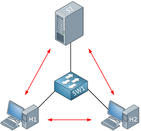
Take a look at the picture above. We have two computers, one switch, and one server. Nothing fancy here…everything is in one VLAN, and the two computers and server can communicate with each other.
What if I want to enhance security and ensure that H1 and H2 can only reach the server but not each other? This makes perfect sense in a client-server network. Normally there is no need for computers to connect to each other (unless Bob and Jane are secretly using shared folders on their computers without permission from the Windows administrator).
We can ensure H1 and H2 cannot communicate with each other by using protected ports. By default, all switch ports are unprotected. Here’s what it looks like:
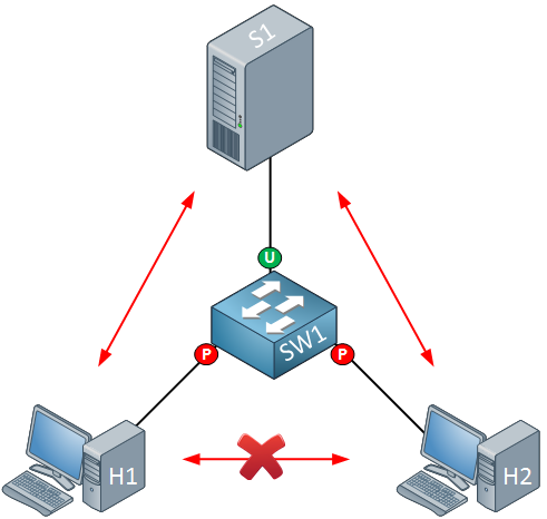
The interfaces connected to H1 and H2 are protected ports, and the interface connected to the server is an unprotected port. Protected ports are unable to communicate with each other. It might also be a good idea to protect your servers with protected ports:
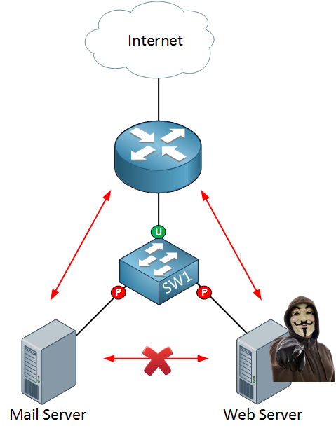
If a freedom fighter hacker takes over your web server, you can reduce the attack surface by preventing them from connecting to other servers in your network.
This should give you an idea of what a protected port does. Let’s look at the actual configuration!
Configuration
To demonstrate this, we will use three computers connected to a single switch:
- All computers are in the same subnet (192.168.1.0 /24)
- All computers are in the same VLAN.
- The switch has a default configuration.
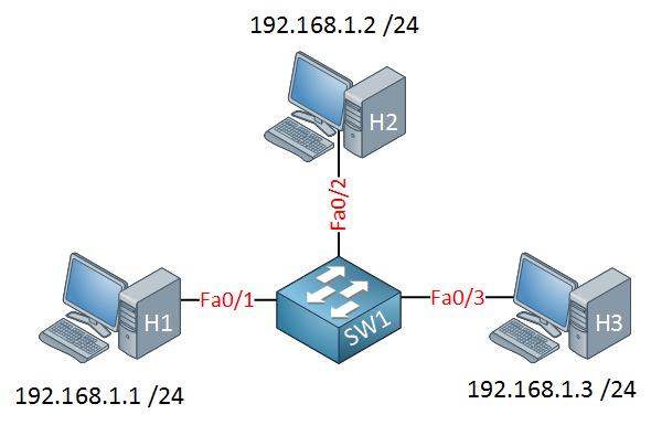
With the default configuration on the switch, all computers are in the same VLAN, so they can ping each other:
protected port on steroids
I also enjoyed the term
Hi Reno,
Very Simple and Great explanation !
Regards,
Srini
lol freedom fighter.
lol protected port on steroids.
LOL! haha
Hello Rene,
Is the Protected option is available in Switch types like 2960 , 3560 ? if yes, i try to applied it on packet tracer which support both switch but it said not supported. Would you please let me know which switch is supported. Thank you