Lesson Contents
In a previous lesson, I explained the differences between classic and rapid spanning tree and how rapid spanning tree works. If you haven’t seen it before, I would recommend looking at it first before diving into the configuration.
Having said that, let’s look at the configuration. This is the topology that I will use:
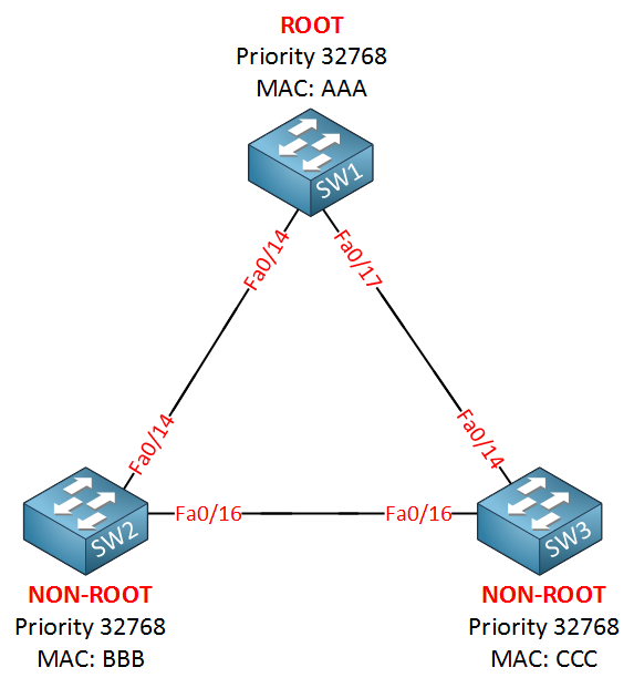
This is the topology I’m going to use. SW1 will be the root bridge in my example. First, we have to enable rapid spanning tree:
SW1(config)#spanning-tree mode rapid-pvstSW2(config)#spanning-tree mode rapid-pvstSW3(config)#spanning-tree mode rapid-pvstThat’s it…just one command will enable rapid spanning tree on our switches. The implementation of rapid spanning tree is rapid-pvst. We are calculating a rapid spanning tree for each VLAN.
Sync Mechanism
First, I want to show you the sync mechanism. Let’s shut the interfaces on SW1:
SW1(config)#interface fa0/14
SW1(config-if)#shutdown
SW1(config)#interface f0/17
SW1(config-if)#shutdown
To see things in action, we’ll enable a debug:
SW1#debug spanning-tree events
Spanning Tree event debugging is onSW2#debug spanning-tree events
Spanning Tree event debugging is onSW3#debug spanning-tree events
Spanning Tree event debugging is onNow I will enable one of the interfaces on SW1:
SW1(config)#interface fa0/14
SW1(config-if)#no shutdown
Here’s what we see:
SW1#
setting bridge id (which=3) prio 4097 prio cfg 4096 sysid 1 (on) id 1001.0011.bb0b.3600
RSTP(1): initializing port Fa0/14
RSTP(1): Fa0/14 is now designated
RSTP(1): transmitting a proposal on Fa0/14
The fa0/14 interface on SW1 will be blocked and it’ll send a proposal to SW2.
SW2#
RSTP(1): initializing port Fa0/14
RSTP(1): Fa0/14 is now designated
RSTP(1): transmitting a proposal on Fa0/14
RSTP(1): updt roles, received superior bpdu on Fa0/14
RSTP(1): Fa0/14 is now root port
SW2 thought it was the root bridge, so it set its Fa0/14 port as designated. However, it received a superior BPDU on this interface. Thus, it no longer considers itself as the root bridge and changes the role of Fa0/14 to the root port. The fa0/16 interface on SW2 will now go into sync mod:
SW2# RSTP(1): syncing port Fa0/16This is the interface that connects to SW3. SW2 will respond to SW1 by sending an agreement:
SW2#  RSTP(1): synced Fa0/14
RSTP(1): transmitting an agreement on Fa0/14 as a response to a proposal
We can see this on SW1 as well:
SW1# RSTP(1): received an agreement on Fa0/14
%LINK-3-UPDOWN: Interface FastEthernet0/14, changed state to up
%LINEPROTO-5-UPDOWN: Line protocol on Interface FastEthernet0/14, changed state to up
SW1 receives the agreement from SW2 and interface fa0/14 will go into forwarding. SW2 will also send a proposal to SW3:
SW2# RSTP(1): transmitting a proposal on Fa0/16When SW3 receives it, it will send an agreement:
SW3# RSTP(1): transmitting an agreement on Fa0/16 as a response to a proposalSW2 receives the agreement from SW3:
SW2# RSTP(1): received an agreement on Fa0/16
%LINK-3-UPDOWN: Interface FastEthernet0/14, changed state to up
%LINEPROTO-5-UPDOWN: Line protocol on Interface FastEthernet0/14, changed state to up
SW2 receives the agreement from SW3, and the interface will go into forwarding. That’s all there to is it…a quick number of handshakes, and the interfaces will move to forwarding without the use of any timers.
Port States
Let’s continue. I’m going to enable this interface so that connectivity is fully restored:
SW1(config)#interface fa0/17
SW1(config-if)#no shutdown
Let’s look at an overview:
SW1#show spanning-tree
VLAN0001
Spanning tree enabled protocol rstp
Root ID Priority 4097
Address 0011.bb0b.3600
This bridge is the root
Hello Time 2 sec Max Age 20 sec Forward Delay 15 sec
Bridge ID Priority 4097 (priority 4096 sys-id-ext 1)
Address 0011.bb0b.3600
Hello Time 2 sec Max Age 20 sec Forward Delay 15 sec
Aging Time 300
Interface Role Sts Cost Prio.Nbr Type
------------------- ---- --- --------- -------- --------------------------------
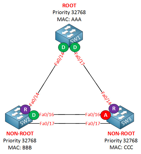
Fa0/14 Desg FWD 19 128.16 P2p
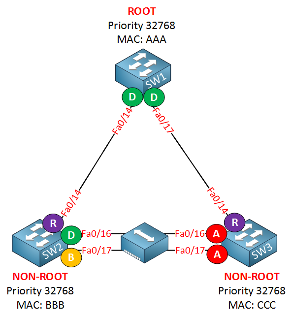
Fa0/17 Desg FWD 19 128.19 P2pWe can verify that SW1 is the root bridge. This show command also reveals that we are running rapid spanning tree. Note that the link type is p2p. This is because my FastEthernet interfaces are in full duplex by default. Let’s run the same command on the other two switches:
SW2#show spanning-tree

VLAN0001
  Spanning tree enabled protocol rstp
  Root ID    Priority    4097
             Address     0011.bb0b.3600
             Cost        19
             Port        16 (FastEthernet0/14)
             Hello Time   2 sec  Max Age 20 sec  Forward Delay 15 sec

  Bridge ID  Priority    8193   (priority 8192 sys-id-ext 1)
             Address     0019.569d.5700
             Hello Time   2 sec  Max Age 20 sec  Forward Delay 15 sec
             Aging Time 300

Interface           Role Sts Cost      Prio.Nbr Type
------------------- ---- --- --------- -------- --------------------------------
Fa0/14              Root FWD 19        128.16   P2p
Fa0/16 Desg FWD 19 128.18 P2pSW3#show spanning-tree
VLAN0001
Spanning tree enabled protocol rstp
Root ID Priority 4097
Address 0011.bb0b.3600
Cost 19
Port 14 (FastEthernet0/14)
Hello Time 2 sec Max Age 20 sec Forward Delay 15 sec
Bridge ID Priority 32769 (priority 32768 sys-id-ext 1)
Address 000f.34ca.1000
Hello Time 2 sec Max Age 20 sec Forward Delay 15 sec
Aging Time 300
Interface Role Sts Cost Prio.Nbr Type
---------------- ---- --- --------- -------- --------------------------------
Fa0/14 Root FWD 19 128.14 P2p
Fa0/16 Altn BLK 19 128.16 P2pHere are SW2 and SW3. Nothing new here. It’s the same information as classic spanning tree. Here’s what the topology looks like now:

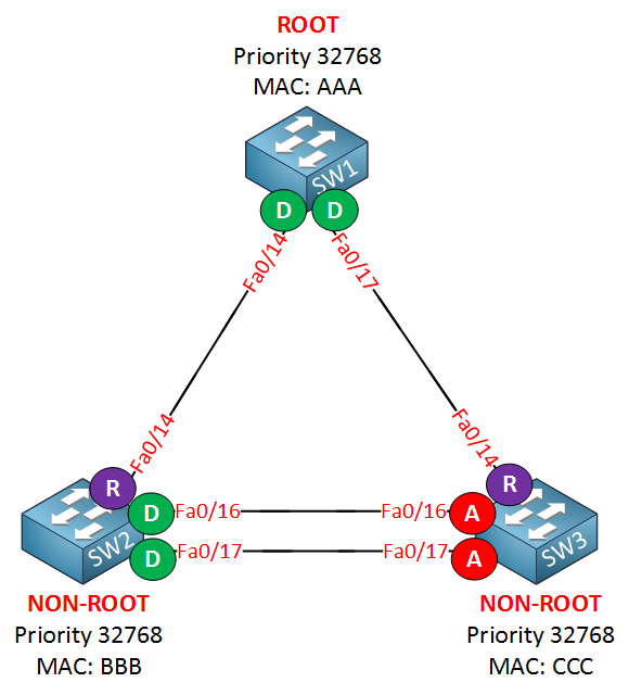
Let’s add another link between SW2 and SW3 to see if this influences our topology:
SW2#show spanning-tree | begin Interface
Interface           Role Sts Cost      Prio.Nbr Type
------------------- ---- --- --------- -------- --------------------------------
Fa0/14              Root FWD 19        128.16   P2p
Fa0/16              Desg FWD 19        128.18   P2p
Fa0/17 Desg FWD 19 128.19 P2pSW3#show spanning-tree | begin Interface
Interface Role Sts Cost Prio.Nbr Type
---------------- ---- --- --------- -------- --------------------------------
Fa0/14 Root FWD 19 128.14 P2p
Fa0/16 Altn BLK 19 128.16 P2p
Fa0/17 Altn BLK 19 128.17 P2pNothing spectacular, we just have another designated port on SW2 and another alternate port on SW3. Let me add that alternate port to the topology:
So far, the topology with rapid spanning tree looks the same as with classic spanning tree. Now let me show you something you haven’t seen before. I will add a hub between SW2 and SW3:
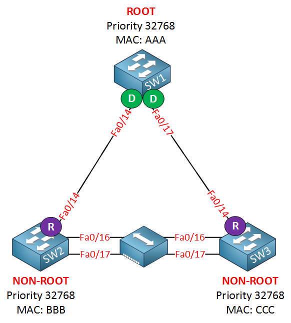
Now take a look again at the interfaces:
SW2#show spanning-tree | begin Interface

Interface           Role Sts Cost      Prio.Nbr Type
------------------- ---- --- --------- -------- --------------------------------
Fa0/14               Root FWD 19        128.5    P2p
Fa0/16               Desg FWD 100       128.3    Shr
Fa0/17 Back BLK 100 128.4 Shr SW3#show spanning-tree | begin Interface
Interface Role Sts Cost Prio.Nbr Type
--------- -------- --------------------------------
Fa0/14 Root FWD 19 128.5 P2p
Fa0/16 Altn BLK 100 128.3 Shr
Fa0/17 Altn BLK 100 128.4 ShrHere’s something new. SW2 has a backup port. Because of the hub in the middle, SW2 and SW3 will hear their own BPDUs.
You can also see that the link type is shr (shared). That’s because the hub causes these switches to switch their interfaces to half duplex. Here’s the topology picture again:
You probably won’t ever see the backup port on a production network since hubs are scarce now, but if you see it, you’ll know why…
BPDU
BPDUs are sent every two seconds (hello time), and if you want to prove this, you can take a look at a debug:
SW2#debug spanning-tree bpduYou can use the debug spanning-tree bpdu command to view BPDUs that are sent or received.
SW2#
STP: VLAN0001 rx BPDU: config protocol = rstp, packet from FastEthernet0/14  , linktype IEEE_SPANNING , enctype 2, encsize 17
STP: enc 01 80 C2 00 00 00 00 11 BB 0B 36 10 00 27 42 42 03
STP: Data     000002023C10010011BB0B36000000000010010011BB0B360080100000140002000F00
STP: VLAN0001 Fa0/14:0000 02 02 3C 10010011BB0B3600 00000000 10010011BB0B3600 8010 0000 1400 0200 0F00
RSTP(1): Fa0/14 repeated msg
RSTP(1): Fa0/14 rcvd info remaining 6
RSTP(1): sending BPDU out Fa0/16
RSTP(1): sending BPDU out Fa0/17
STP: VLAN0001 rx BPDU: config protocol = rstp, packet f
You will see the contents of the BPDU above. It’s not very useful if you want to know the content of the BPDU, but it does show us that SW2 is receiving BPDUs and sending them on its interfaces.
Packet Capture: Spanning Tree BPDU
Link Failures
Let’s get rid of the hub and do something else…I will simulate a link failure between SW1 and SW3 to see how rapid spanning tree deals with this.
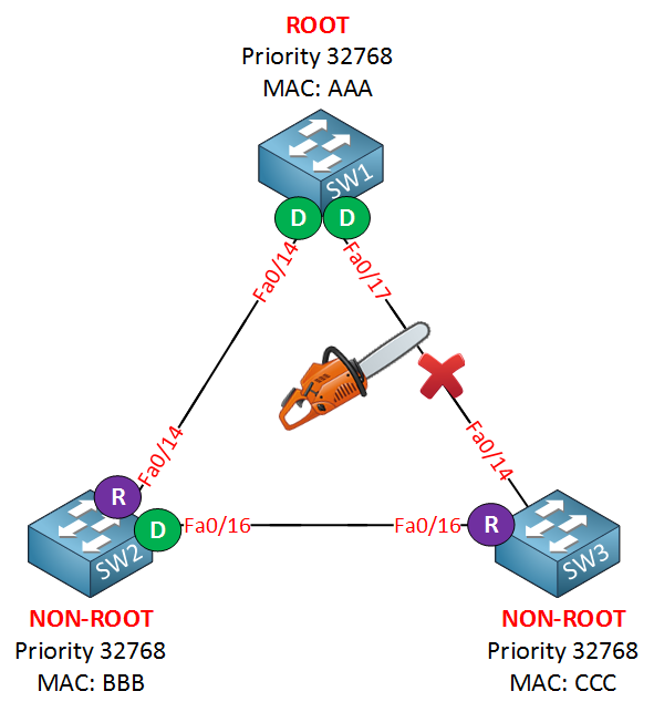
First, I’m going to shut the fa0/17 interface on SW1:
SW1(config)#interface fa0/17
SW1(config-if)#shutdown
You’ll see this on SW3:
SW3#
RSTP(1): updt rolesroot port Fa0/14 is going down
RSTP(1): Fa0/16 is now root port
SW3 realized something is wrong with the root port almost immediately and will change the fa0/16 interface from alternate port to root port. This is the equivalent of UplinkFast for classic spanning tree but it’s enabled by default for rapid spanning tree.
Nice explanation, Rene.
You nicely described in STP, how the affected switch updated CAM table.
When a link fails (Uplink/Backbone) in RSTP environment, how the affected switch will collect MAC?
Hi Betar,
Here’s an example how the MAC addresses are updated for uplink failures:
https://networklessons.com/spanning-tree/spanning-tree-uplinkfast
Uplinkfast can be enabled for “classic” STP but a similar mechanism is built-in RSTP.
Backbone fast is also a good read:
https://networklessons.com/spanning-tree/spanning-tree-backbone-fast
A similar mechanism is built in for RSTP.
Rene
Rene,
Hi. In the last part of the lesson you convert switch B to PVST mode - what is the impact to the network - does computer A lose connectivity to the rest of the network outside of switch B for 30 seconds? What about if there was a host connected off of switch A and another host connected off switch B - they would still continue to communicate throughout the change of switch B to PVST mode?
Many thanks,
Thomas
Hi Thomas,
I just tried this, 3 switches and two hosts (one on SW1 and SW2). If you switch to any of the STP mode, you have donwtime. When I change one switch from RPVST to PVST+ then you see the interfaces going through the listening and learning states again.
When all switches are running PVST+ and I turn one of them into RPVST, you see it sending and waiting for proposals. It’s all compatible but expect your interfaces to be blocked for a moment
Rene
Hi Rene,
Pasting the debug msgs:
what does it mean ? I’m not able to understand.