Lesson Contents
Spanning tree (STP) is a protocol to prevent loops in an Ethernet network. Its goal is to create a loop-free topology. Radia Perlman created STP in the 1980s, so it’s been around for a while. We’ve had multiple versions, such as PVST, RSTP, RPVST, and MST.
STP is somewhat plug-and-play. Even without configuration, you’ll end up with a loop-free L2 topology.
We’ve used STP for a long time, but networks are different nowadays. STP isn’t suitable anymore for more complex environments such as data centers.
In this lesson, I’ll give you an overview of STP’s limitations.
Limitations
Unused interfaces
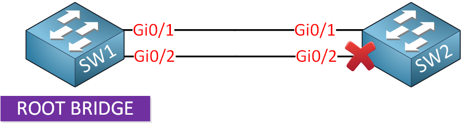
STP blocks redundant interfaces to create a loop-free topology, including multiple uplinks between switches. Unfortunately, this means we can’t use the available bandwidth on these interfaces. You can use PVST or MST and different root bridges for each VLAN or group of VLANs, but it’s not ideal. You’ll be able to send traffic for different VLANs on different interfaces, but you won’t be able to utilize both interfaces fully.
Link aggregation, such as EtherChannel, works around this issue because STP sees the aggregated link as a single logical interface.
Suboptimal paths
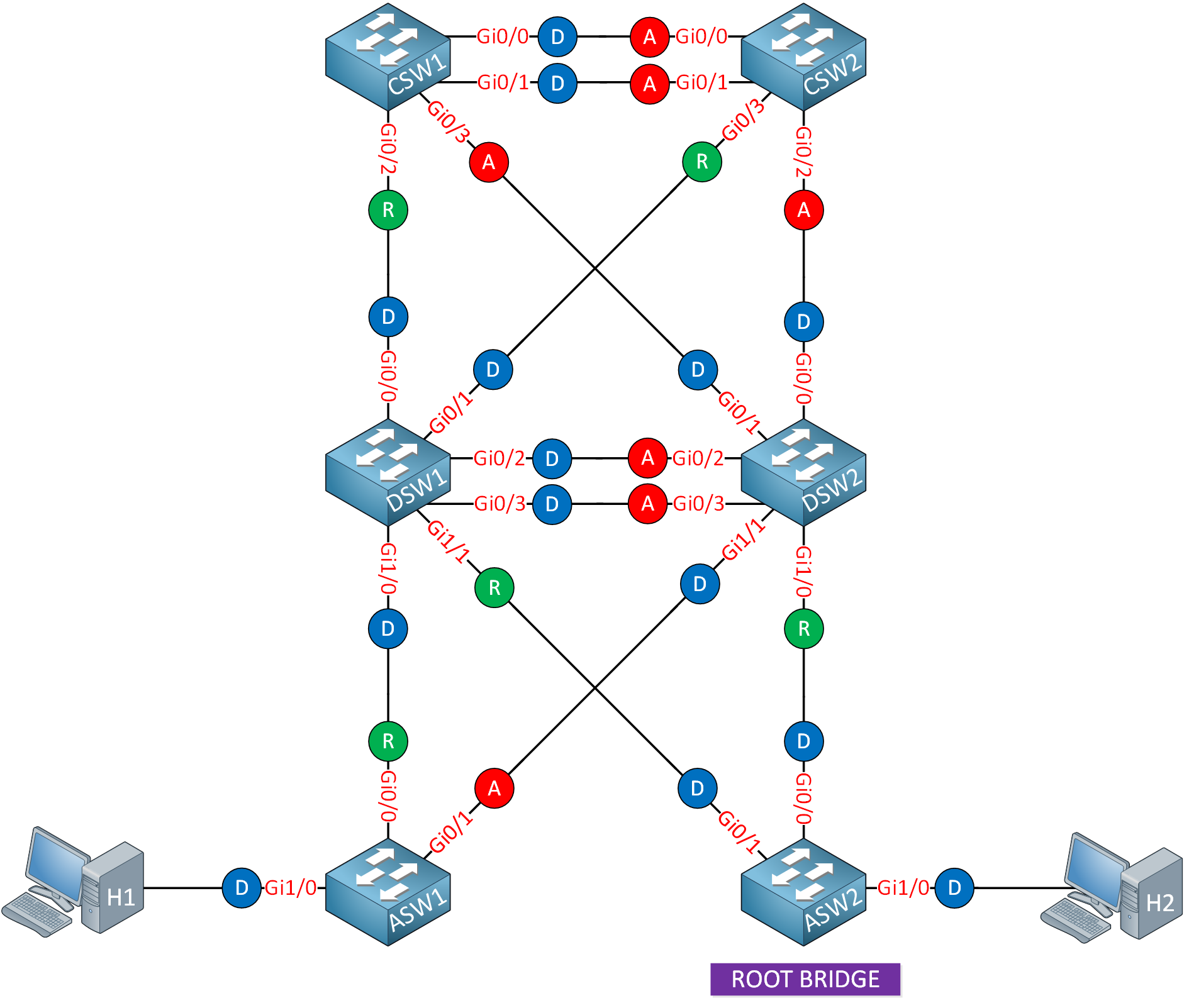
The root bridge plays an important role in STP. The root bridge is selected based on the lowest bridge ID, which is a combination of priority and MAC address. If the root bridge is not the most optimal switch in the network topology, it can lead to suboptimal paths. Misconfiguration or default settings of switchport path cost and port priority can also result in suboptimal paths. Let me give you an example. Here is the topology of a campus network where ASW2 has become the root bridge:
Here’s the topology with all blocked interfaces removed:
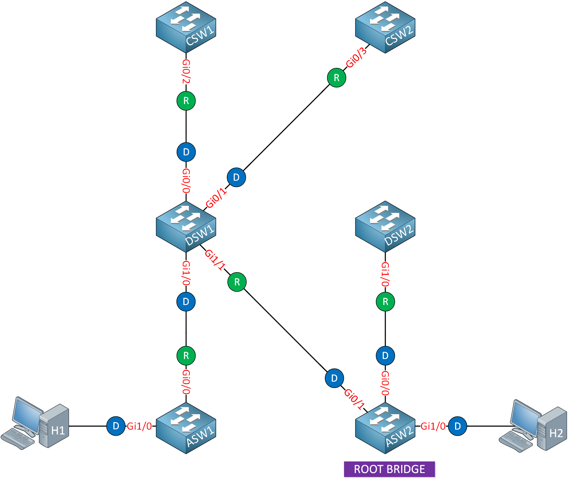
As you can see, DSW2 selected its interface that connects to ASW2 as the root port and blocked all other interfaces. Traffic from DSW2 has to go through ASW2 if it wants to go anywhere. This is not the most optimal path. Also, the access layer switches are likely less powerful than the distribution layer switches. ASW2 could run out of CPU cycles and memory, and its interfaces could become congested.
Suboptimal paths can result in higher latency and reduced network performance.
Slow Convergence
In the event of an interface or switch failure, STP has to recalculate the tree. When a root bridge fails, STP has to figure out what the next best root bridge is. When switches receive a topology change notification (TCN), they clear their MAC address tables and have to relearn MAC addresses. This recalculation takes time and impacts convergence times.
One of STP’s drawbacks is its slow convergence time. It can take up to 50 seconds to restore after an interface failure. This delay is problematic for time-sensitive applications such as VoIP and high-bandwidth interfaces. With 10G, 40G, or 100G interfaces, you get many packet drops in a short while.
You can tweak some of STP’s timers to reduce the convergence time, but that’s it.
Equal-Cost MultiPath (ECMP)
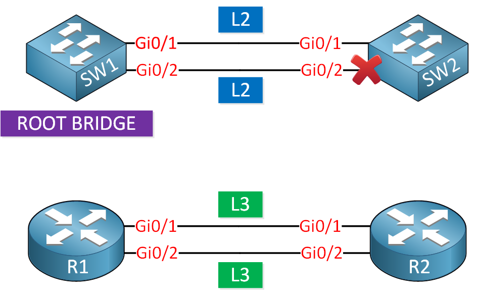
To prevent loops, STP blocks all redundant links, allowing only a single active path between two switches. This ensures there is no loop, but it also means we don’t have Equal-Cost MultiPath (ECMP) routing. This results in the underutilization of available bandwidth, and it’s a major disadvantage compared to L3 networks, where most routing protocols support ECMP.
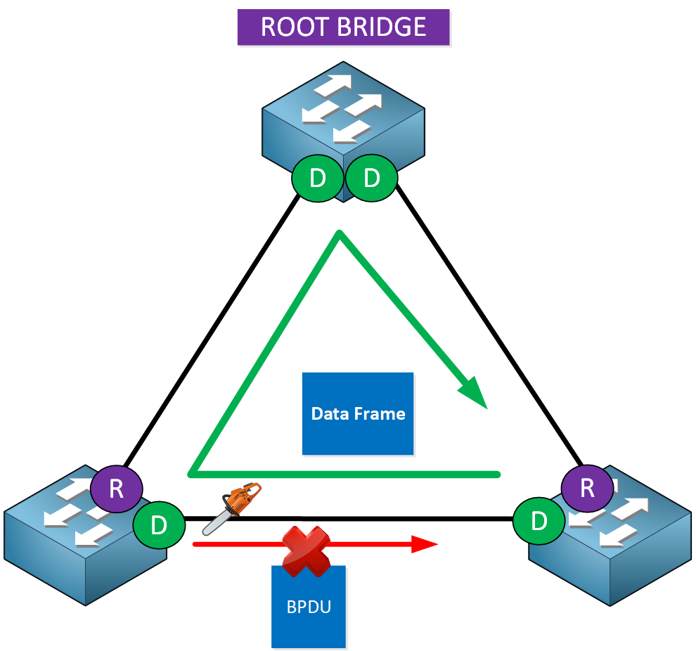
Broadcast Storms
Traffic originating from one switch should never be sent back to the same switch. However, loops can occur in certain scenarios, even if STP has been configured correctly. This can happen with something as simple as a malfunctioning NIC.
When traffic loops forever, we call it a broadcast storm. This can take down the entire network. The L2 header has no Time to Live (TTL), so once you have a loop, frames will be forwarded forever until the hardware can’t handle it anymore.
L3 networks don’t have this issue because IP packets have a TTL value. When the TTL reaches 0, the packet is dropped.
Broadcast storms are one reason why keeping the size of your broadcast domains small is a good idea. It reduces the blast radius when a broadcast storm occurs.
Dual-Homing
Because STP blocks redundant interfaces, you also can’t connect an endpoint like a host or server to more than one switch. If you do, one of the two interfaces is blocked. When the primary link goes down, traffic to and from the endpoint is dropped until STP recalculates the tree.
Some technology helps to work around this limitation of STP, such as:
- Cross-Stack EtherChannel
- StackWise (Virtual)
- Virtual Switching System (VSS)
- Multichassis Etherchannel (MEC)
- Virtual PortChannel (vPC)
- Multichassis Link Aggregation Control Protocol (mLACP)
Here’s an example of vPC:
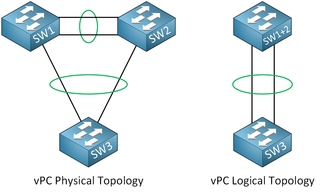
To SW3, it’s as SW1 and SW2 are a single switch.
Network Scalability
VLANs have a 12-bit identifier, which allows us to create 4094 VLANs (give or take because there are excluded and reserved VLANs). This might sound like a lot, but it isn’t for modern networks. Let me give you a simple example to illustrate this. Imagine we have a small data center that consists of the following:
- 200 physical servers
- 20 VMs per physical server
- 2 services per VM that require a unique VLAN.
We’ll have:
- 200 servers x 20 VMs = 4000 VMs.
- 4000 VMs x 2 VLANs = 8000 VLANs.
In this scenario, we would need 8000 VLANs, but we can only create up to 4094 VLANs. Therefore, we won’t have enough available VLANs for a small data center like this.
Also, STP becomes difficult to manage in larger and more complex networks. You must configure the root bridge, path costs, and port priorities. You also need to configure features such as:
Troubleshooting
STP issues can be difficult to detect and troubleshoot. Loss of BPDUs, interface issues, or misconfigurations can cause bridging loops. Finding and solving these issues requires a deep understanding of STP and network monitoring.
Conclusion
Now you know about the limitations of STP:
- Unused interfaces:
- Redundant interfaces are blocked, leading to underutilized bandwidth.
- Link aggregation is a workaround.
- Suboptimal paths:
- Root bridge selection can lead to suboptimal path selection.
- Slow convergence:
- Recalculation of the tree is slow.
- Problematic for time-sensitive applications.
- No ECMP
- Redundant interfaces are blocked.
- Underutilization of available bandwidth.
- Broadcast storms
- Loops can cause broadcast storms, which can take down the network.
- L2 headers lack TTL.
- No dual-homing
- Redundant interfaces are blocked, which prevents dual-homing.
- vPC, VSS, and related technology are workarounds.
- Network scalability issues:
- Insufficient VLANs because of 12-bit identifier.
- Managing STP in large networks is challenging.
- STP features required such as root bridge, path costs, port priorities, root guard, BPDU filter, BPDU guard, portfast, etc.
However, there is still demand for large scalable L2 networks. Some applications require that hosts or servers are in the same subnet. This is one of the reasons why VXLAN has become popular.