Lesson Contents
Multiple Spanning Tree (MST) is a spanning tree variant that allows you to map multiple VLANs to a single STP instance. Classic STP, PVST+, and Rapid PVST+ calculate an STP topology for each VLAN. When you have 20 VLANs, it means there are 20 STP instances. When you have many VLANs, using MST reduces CPU and memory usage because you’ll need fewer STP instances.
In this lesson, I’ll explain how MST works and how to configure it on Cisco Catalyst switches.
Key Takeaways
- MST groups VLANs into instances where multiple VLANs share a STP calculation. This saves CPU and memory resources.
- Instance 0 (IST) is the Internal Spanning Tree (IST) and mandatory. This creates the loop-free topology within the MST region.
- The IST uses rapid spanning tree.
- Regions require matching attributes:
- Identical MST name
- revision number
- VLAN-to-instance mapping
- Each instance can have a different root bridge for load balancing.
- External switches only see one topology because MST advertises the IST to PVST+ or Rapid PVST+ switches.
Prerequisites
To understand MST, you’ll need to be familiar with:
Explanation
Let’s take a look at an example:
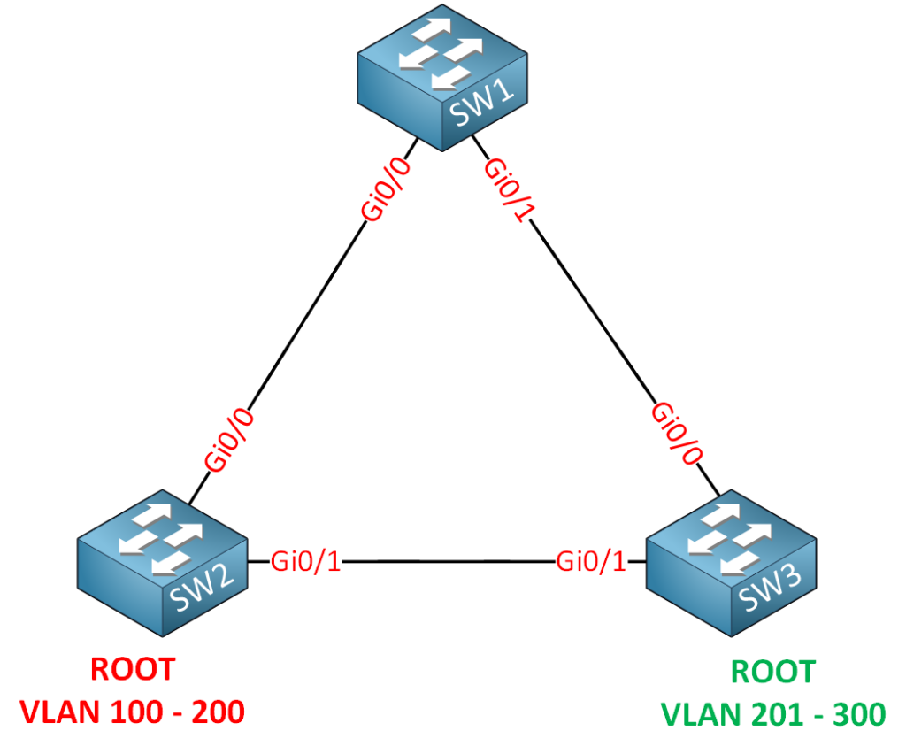
Take a look at the topology above. We have three switches and a lot of VLANs. There are 201 VLANs in total. If we are running PVST or Rapid PVST, we have 201 different calculations for each VLAN. This requires a lot of CPU power and memory.
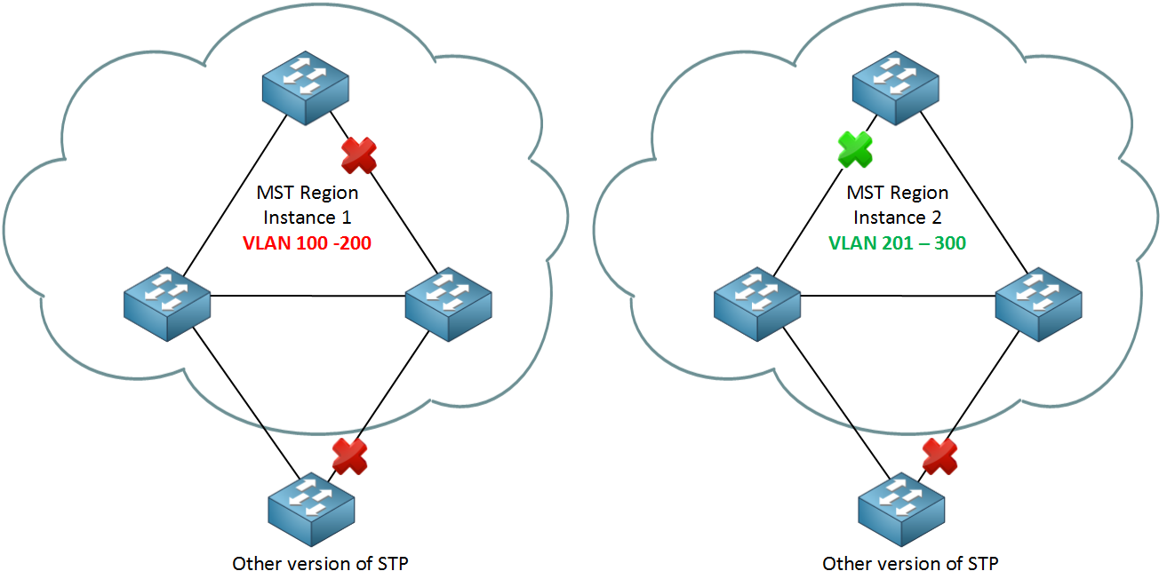
When SW2 is the root bridge for VLAN 100 – 200 and SW3 for VLAN 201 – 300, our spanning tree topologies will look like this:
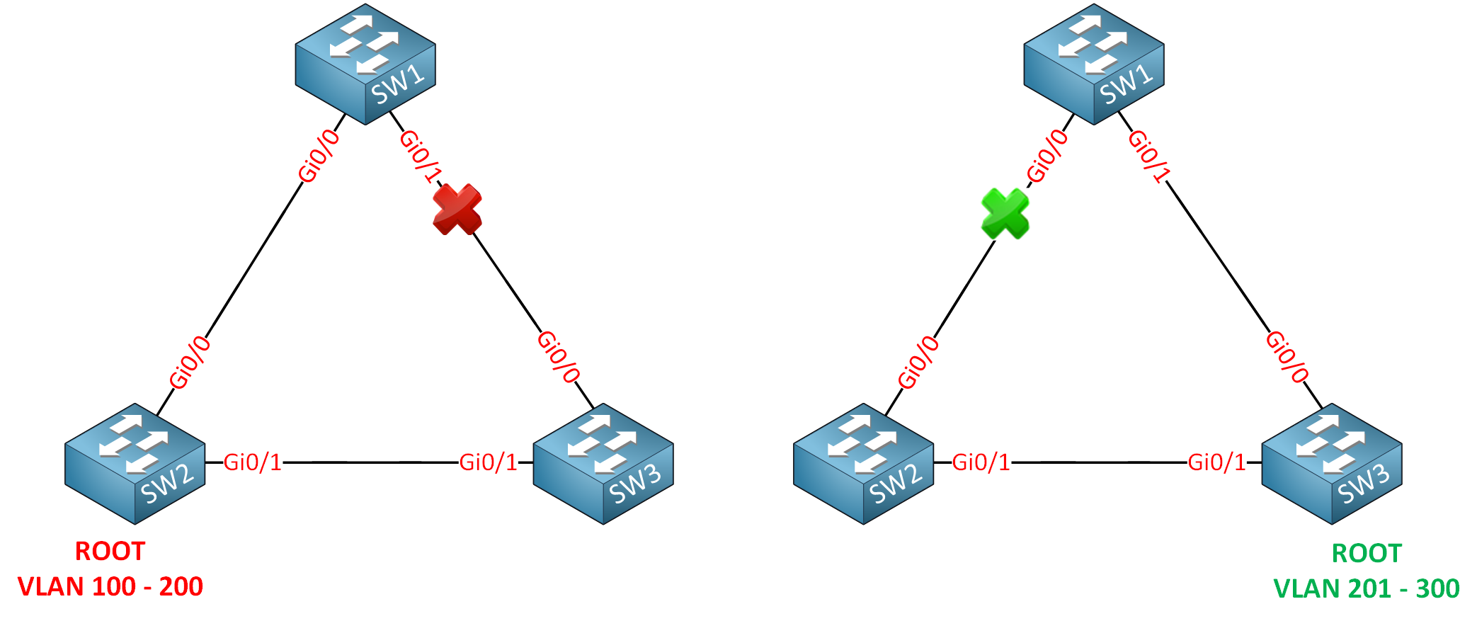
SW2 is the root bridge for VLAN 100 up to VLAN 200. This means that the GigabitEthernet0/1 interface on SW1 or the GigabitEthernet 0/0 interface of SW3 will be blocked. I’ll have 100 spanning tree calculations, but they all look the same for these VLANs…
The same thing applies to VLAN 201 – 300. SW3 is the root bridge for VLAN 201 up to 300. The GigabitEthernet 0/0 interface on SW1 or SW2 will be blocked for all these VLANs.
Two different outcomes, but I still have 200 different instances of spanning tree running. That’s a waste of CPU cycles and memory.
MST (Multiple Spanning Tree) will solve this issue. Instead of calculating a spanning tree for each VLAN, we can use instances and map VLANs to each instance. For the network above, I could do something like this:
- Instance 1: VLAN 100 – 200
- Instance 2: VLAN 201 – 300
Sounds logical, right? Only two spanning tree calculations (instances) are required for all these VLANs.
MST works with the concept of regions. Switches configured to use MST need to find out if their neighbors are running MST.
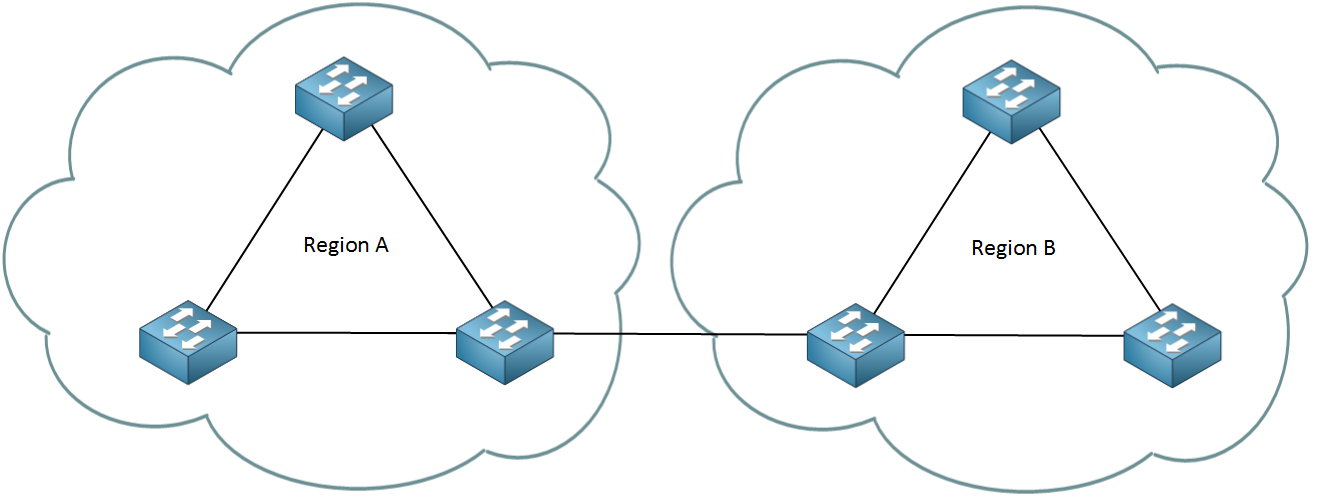
When switches have the same attributes, they will be in the same region. It’s possible to have one or more regions. Here are the attributes that need to match:
- MST configuration name.
- MST configuration revision number.
- MST instance to VLAN mapping table.
When switches have the same attributes configured, they will be in the same region. If the attributes are different, the switch is seen as being at the region’s boundary. It can be connected to another MST region but also talk to a switch running another version of spanning tree.
The MST configuration name is just something you can make up. It’s used to identify the MST region. The MST configuration revision number is also something you can make up, and the idea behind this number is that you can change the number whenever you change your configuration. It doesn’t matter what you pick as long as it’s the same on all switches within the MST region. VLANs will be mapped to an instance using the MST instance to VLAN mapping table. This is something we have to do ourselves.
Within the MST region, we will have one instance of spanning tree that will create a loop-free topology within the region. When you configure MST, there is always one default instance used to calculate the topology within the region. We call this the IST (Internal Spanning Tree). By default, Cisco will use instance 0 to run the IST. The IST runs rapid spanning tree.
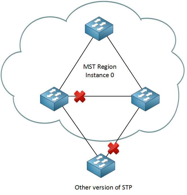
I could create instances 1 for VLAN 100 – 200 and 2 for VLAN 201 – 300. Depending on which switch becomes the root bridge for each instance, a different port will be blocked. It could look like this:
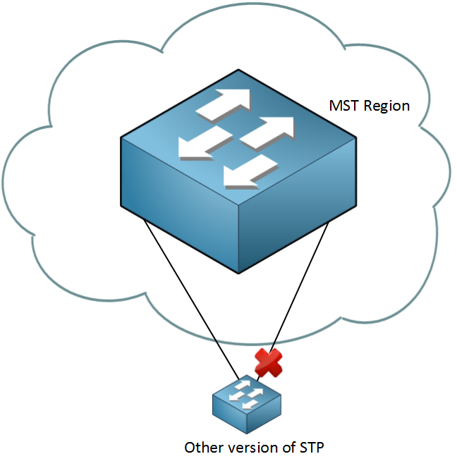
The switch outside the MST region doesn’t see what the MST region looks like. For this switch, it’s like it’s talking to one big switch or a ‘black box’:
If you want to know the details of how MST and PVST+ work together, check out our MST and PVST+ interoperability lesson. Let’s have some fun with the configuration.
MST Configuration
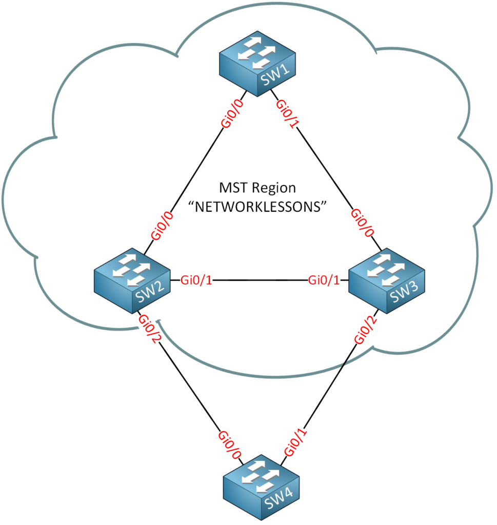
I will use the following topology:
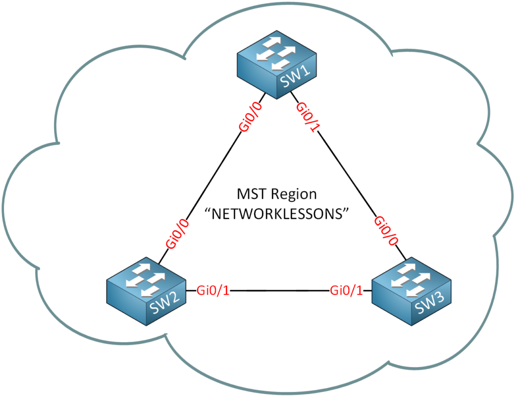
We’ll start with a single MST region with the following attributes:
- MST configuration name: “NETWORKLESSONS”
- MST configuration revision number: 1 (this is just a number that I made up)
- MST instance to VLAN mapping table:
- Instance 1: VLAN 10, 20, and 30.
- Instance 2: VLAN 40, 50, and 60.
This is what we will do:
SW1(config)#spanning-tree mode mstSW2(config)#spanning-tree mode mstSW3(config)#spanning-tree mode mstThis is how we enable MST on our switches. Let’s look at the default MST instance:
SW1#show spanning-tree mst configuration
Name      []
Revision  0     Instances configured 1

Instance  Vlans mapped
--------  ---------------------------------------------------------------------
0         1-4094
-------------------------------------------------------------------------------SW2#show spanning-tree mst configuration
Name []
Revision 0 Instances configured 1
Instance Vlans mapped
-------- ---------------------------------------------------------------------
0 1-4094
-------------------------------------------------------------------------------SW3#show spanning-tree mst configuration
Name []
Revision 0 Instances configured 1
Instance Vlans mapped
-------- ---------------------------------------------------------------------
0 1-4094
-------------------------------------------------------------------------------
We can use the show spanning-tree mst configuration command to see the MST instances. I haven’t created any additional instances, so only instance 0 is available. You can see that all VLANs are currently mapped to instance 0. Let’s see what else we can find:
SW1#show spanning-tree mst

##### MST0    vlans mapped:   1-4094
Bridge        address 5254.0010.370d  priority      32768 (32768 sysid 0)
Root          address 5254.0001.50c4  priority      32768 (32768 sysid 0)
              port    Gi0/0           path cost     0
Regional Root address 5254.0001.50c4  priority      32768 (32768 sysid 0)
                                      internal cost 20000     rem hops 19
Operational   hello time 2 , forward delay 15, max age 20, txholdcount 6
Configured    hello time 2 , forward delay 15, max age 20, max hops    20

Interface        Role Sts Cost      Prio.Nbr Type
---------------- ---- --- --------- -------- --------------------------------
Gi0/0            Root FWD 20000     128.1    P2p
Gi0/1            Desg FWD 20000     128.2    P2p
You can also use the show spanning-tree mst command. We can see the VLAN mapping but also information about the root bridge. Before we can add more instances, we have to do our chores…time to add some VLANs and configure the links between the switches as trunks:
SW1(config)#interface GigabitEthernet 0/0
SW1(config-if)#switchport trunk encapsulation dot1q
SW1(config-if)#switchport mode trunk
SW1(config)#interface GigabitEthernet 0/1
SW1(config-if)#switchport trunk encapsulation dot1q
SW1(config-if)#switchport mode trunkSW2(config)#interface GigabitEthernet 0/0
SW2(config-if)#switchport trunk encapsulation dot1q
SW2(config-if)#switchport mode trunk
SW2(config)#interface GigabitEthernet 0/1
SW2(config-if)#switchport trunk encapsulation dot1q
SW2(config-if)#switchport mode trunkSW3(config)#interface GigabitEthernet 0/0
SW3(config-if)#switchport trunk encapsulation dot1q
SW3(config-if)#switchport mode trunk
SW3(config)#interface GigabitEthernet 0/1
SW3(config-if)#switchport trunk encapsulation dot1q
SW3(config-if)#switchport mode trunkThat takes care of the trunks. Here are the VLANs:
SW1, SW2 & SW3:
(config)#vlan 10
(config-vlan)#vlan 20
(config-vlan)#vlan 30
(config-vlan)#vlan 40
(config-vlan)#vlan 50
(config-vlan)#vlan 60
(config-vlan)#exit
Now we can configure MST and the instances:
SW1(config)#spanning-tree mst configuration
SW1(config-mst)#name NETWORKLESSONS
SW1(config-mst)#revision 1
SW1(config-mst)#instance 1 vlan 10,20,30
SW1(config-mst)#instance 2 vlan 40,50,60
SW1(config-mst)#exitSW2(config)#spanning-tree mst configuration
SW2(config-mst)#name NETWORKLESSONS
SW2(config-mst)#revision 1
SW2(config-mst)#instance 1 vlan 10,20,30
SW2(config-mst)#instance 2 vlan 40,50,60
SW2(config-mst)#exitSW3(config)#spanning-tree mst configuration
SW3(config-mst)#name NETWORKLESSONS
SW3(config-mst)#revision 1
SW3(config-mst)#instance 1 vlan 10,20,30
SW3(config-mst)#instance 2 vlan 40,50,60
SW3(config-mst)#exitThis is how we configure MST. First, you need the spanning-tree mst configuration command to enter the configuration of MST. We set the name by using the name command. Don’t forget to set a revision number and map the instances with the instance command. Let’s verify our work:
SW1#show spanning-tree mst configuration
Name      [NETWORKLESSONS]
Revision  1     Instances configured 3

Instance  Vlans mapped
--------  ---------------------------------------------------------------------
0         1-9,11-19,21-29,31-39,41-49,51-59,61-4094
1         10,20,30
2         40,50,60
-------------------------------------------------------------------------------
We can use the show spanning-tree mst configuration command to verify our configuration. You can see that we now have two instances. The VLANs are mapped to instances 1 and 2. All the other VLANs are still mapped to instance 0.
So far, so good. Let’s play some more with MST and change the root bridge:
I want to ensure that SW1 is the root bridge within our region. We’ll have to change the priority for the IST (Internal Spanning Tree):
SW1(config)#spanning-tree mst 0 priority 4096This is how I change the priority for MST instance 0. Let’s verify this:
SW1#show spanning-tree mst

##### MST0    vlans mapped:   1-9,11-19,21-29,31-39,41-49,51-59,61-4094
Bridge        address 5254.0010.370d  priority      4096  (4096 sysid 0)
Root          this switch for the CIST
Operational   hello time 2 , forward delay 15, max age 20, txholdcount 6
Configured    hello time 2 , forward delay 15, max age 20, max hops    20

Interface        Role Sts Cost      Prio.Nbr Type
---------------- ---- --- --------- -------- --------------------------------
Gi0/0            Desg FWD 20000     128.1    P2p
Gi0/1            Desg FWD 20000     128.2    P2p
Here, you can see that SW1 is the root bridge for the IST. It says CIST (Common and Internal Spanning Tree).
Let’s take a look at the interfaces:
SW1#show spanning-tree mst 0 | begin Interface
Interface        Role Sts Cost      Prio.Nbr Type
---------------- ---- --- --------- -------- --------------------------------
Gi0/0            Desg FWD 20000     128.1    P2p
Gi0/1 Desg FWD 20000 128.2 P2pSW2#show spanning-tree mst 0 | begin Interface
Interface Role Sts Cost Prio.Nbr Type
---------------- ---- --- --------- -------- --------------------------------
Gi0/0 Root FWD 20000 128.1 P2p
Gi0/1 Desg FWD 20000 128.2 P2pSW3#show spanning-tree mst 0 | begin Interface
Interface Role Sts Cost Prio.Nbr Type
---------------- ---- --- --------- -------- --------------------------------
Gi0/0 Root FWD 20000 128.1 P2p
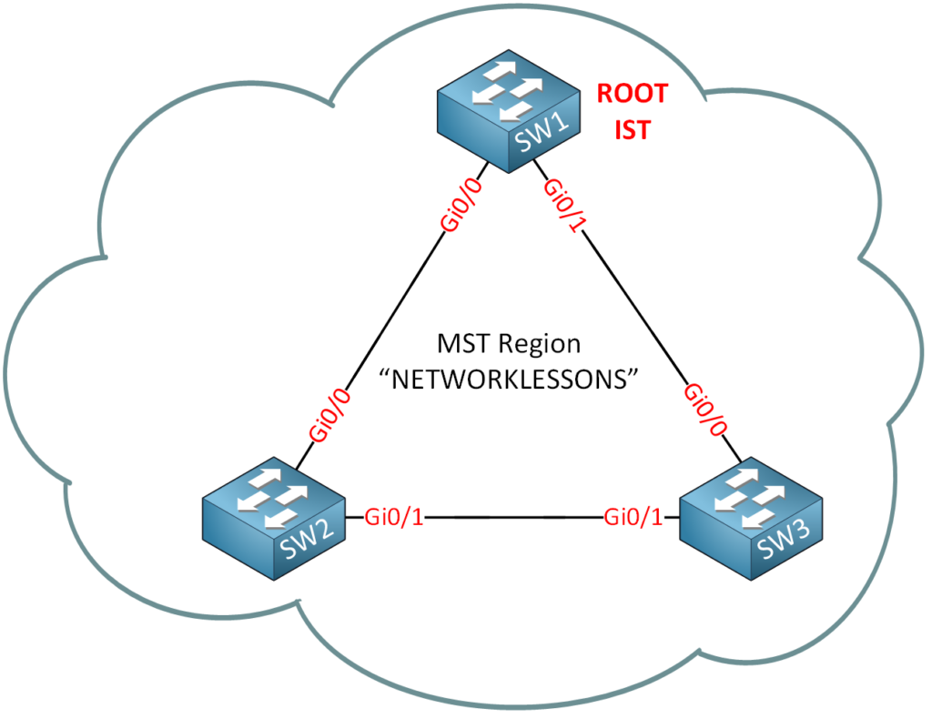
Gi0/1 Altn BLK 20000 128.2 P2pNow, we know the state of all interfaces. Let’s draw a picture so we know what the IST looks like:
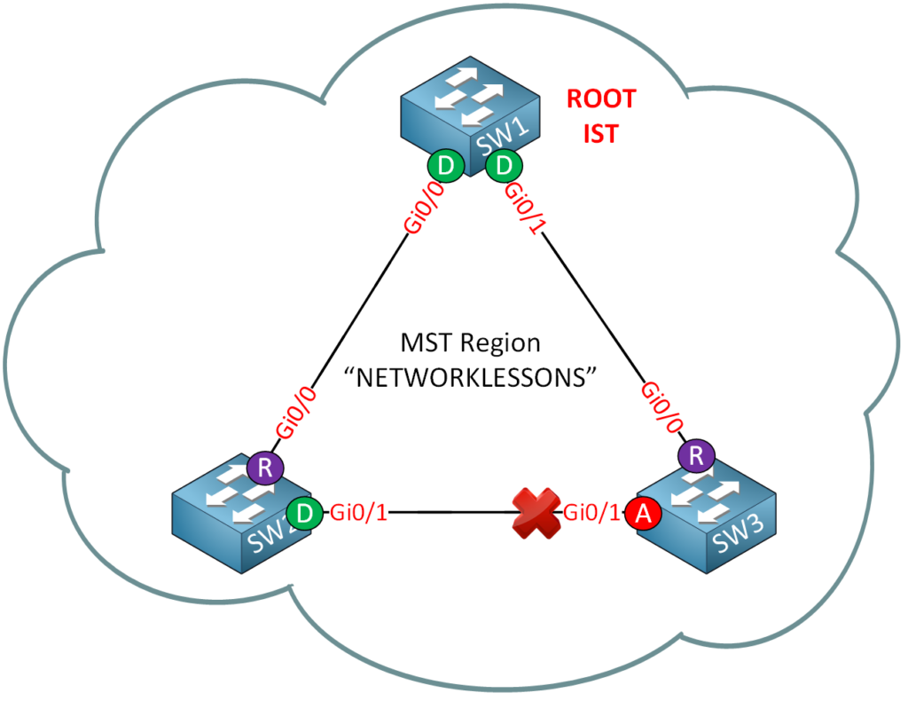
Now I want to make some changes to instance 1 so SW2 will be the root bridge:
SW2(config)#spanning-tree mst 1 priority 4096We’ll change the priority on SW2 for instance 2.
SW2#show spanning-tree mst 1

##### MST1    vlans mapped:   10,20,30
Bridge        address 5254.0001.50c4  priority      4097 (4096 sysid 1)
Root          this switch for MST1

Interface        Role Sts Cost      Prio.Nbr Type
---------------- ---- --- --------- -------- --------------------------------
Gi0/1            Desg FWD 20000     128.2    P2p
This command proves that SW2 is the root bridge for instance 1. Let’s check the interfaces:
SW1#show spanning-tree mst 1 | begin Interface

Interface        Role Sts Cost      Prio.Nbr Type
---------------- ---- --- --------- -------- --------------------------------
Gi0/0            Root FWD 20000     128.1    P2p
Gi0/1 Desg FWD 20000 128.2 P2pSW2#show spanning-tree mst 1 | begin Interface
Interface Role Sts Cost Prio.Nbr Type
---------------- ---- --- --------- -------- --------------------------------
Gi0/0 Desg FWD 20000 128.1 P2p
Gi0/1 Desg FWD 20000 128.2 P2pSW3#show spanning-tree mst 1 | begin Interface
Interface Role Sts Cost Prio.Nbr Type
---------------- ---- --- --------- -------- --------------------------------
Gi0/0 Altn BLK 20000 128.1 P2p
Gi0/1 Root FWD 20000 128.2 P2pThis is what instance 1 looks like. Let’s turn that into a nice picture:
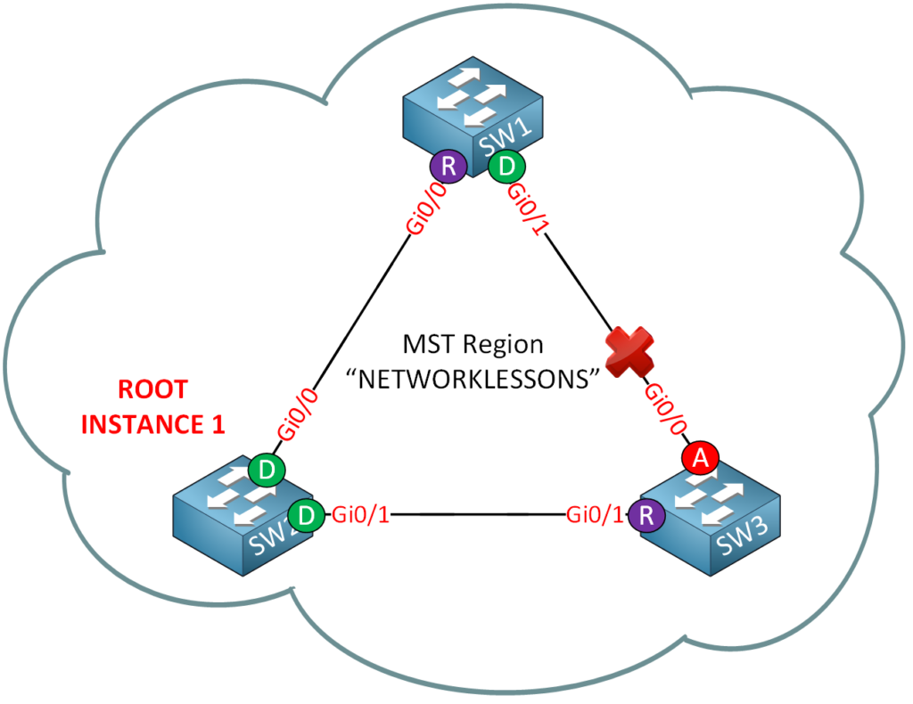
Here’s a picture of instance 1 to show you the port roles. Note that this topology looks different than the one, for instance 0.
Last but not least, I’m now going to make some changes for instance 2:
SW3(config)#spanning-tree mst 2 priority 4096SW3 will become the root bridge for instance 2.
SW3#show spanning-tree mst 2

##### MST2    vlans mapped:   40,50,60
Bridge        address 5254.0016.36f5  priority      4098  (4096 sysid 2)
Root          this switch for MST2

Interface        Role Sts Cost      Prio.Nbr Type
---------------- ---- --- --------- -------- --------------------------------
Gi0/0            Desg FWD 20000     128.1    P2p
Gi0/1            Desg FWD 20000     128.2    P2p
SW3 is now the root bridge for instance 2. Let’s look at the interfaces:
SW1#show spanning-tree mst 2 | begin Interface
Interface        Role Sts Cost      Prio.Nbr Type
---------------- ---- --- --------- -------- --------------------------------
Gi0/0            Altn BLK 20000     128.1    P2p
Gi0/1            Root FWD 20000     128.2    P2p
SW2#show spanning-tree mst 2 | begin Interface
Interface Role Sts Cost Prio.Nbr Type
---------------- ---- --- --------- -------- --------------------------------
Gi0/0 Desg FWD 20000 128.1 P2p
Gi0/1 Root FWD 20000 128.2 P2pSW3#show spanning-tree mst 2 | begin Interface
Interface Role Sts Cost Prio.Nbr Type
---------------- ---- --- --------- -------- --------------------------------
Gi0/0 Desg FWD 20000 128.1 P2p
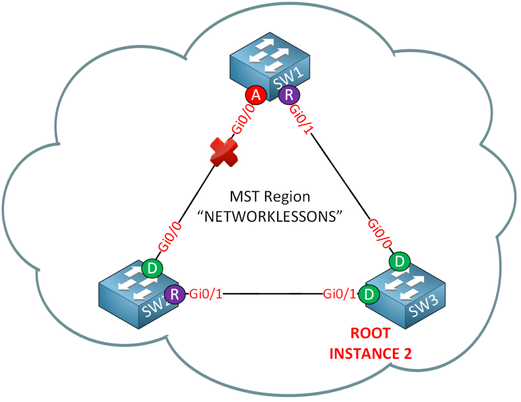
Gi0/1 Desg FWD 20000 128.2 P2pAnd we can draw another topology picture:
Let’s compare instances 1 and 2 next to each other:
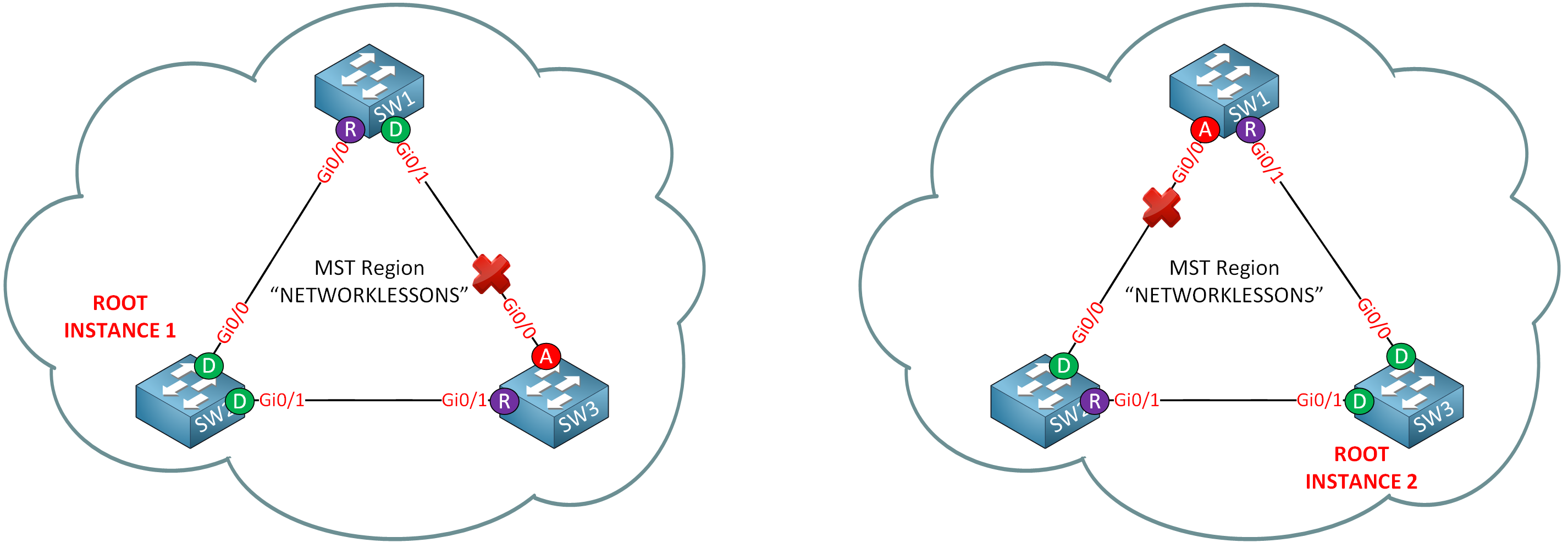
On the left side, you see instance 1; on the right is instance 2.
By changing the root bridge per instance, we end up with different topologies:
- Instance 1: GigabitEthernet0/0 on SW3 is blocked for VLAN 10, 20, and 30.
- Instance 2: GigabitEthernet0/0 on SW1 is blocked for VLAN 40, 50, and 60.
What happens when I add another switch running PVST to our topology? Let’s find out!
I’ll configure the GigabitEthernet0/2 interfaces on SW2 and SW3 as trunks:
SW2(config)#interface GigabitEthernet0/2
SW2(config-if)#switchport trunk encapsulation dot1q
SW2(config-if)#switchport mode trunkSW3(config)#interface GigabitEthernet0/2
SW3(config-if)#switchport trunk encapsulation dot1q
SW3(config-if)#switchport mode trunkAnd we’ll configure the GigabitEthernet0/0 and 0/1 interfaces of SW4 as trunks:
SW4(config)#interface GigabitEthernet0/0
SW4(config-if)#switchport trunk encapsulation dot1q
SW4(config-if)#switchport mode trunkSW4(config)#interface GigabitEthernet0/1
SW4(config-if)#switchport trunk encapsulation dot1q
SW4(config-if)#switchport mode trunkPVST is the default spanning tree mode on Cisco switches, so we don’t have to change this:
SW4#show running-config all | include spanning-tree mode
spanning-tree mode pvst
Let’s add VLAN 10, 20, 30, 40, 50, and 60 on SW4:
SW4(config)#vlan 10
SW4(config-vlan)#vlan 20
SW4(config-vlan)#vlan 30
SW4(config-vlan)#vlan 40
SW4(config-vlan)#vlan 50
SW4(config-vlan)#vlan 60
SW4(config-vlan)#exit
I want to ensure that we have a trunk to SW2 and SW3 and that SW4 knows about all the VLANs. Let’s see what SW4 thinks of all this:
SW4#show spanning-tree vlan 1

VLAN0001
  Spanning tree enabled protocol ieee
  Root ID    Priority    4096
             Address     5254.0010.370d
             Cost        4
             Port        1 (GigabitEthernet0/0)
             Hello Time   2 sec  Max Age 20 sec  Forward Delay 15 sec

  Bridge ID  Priority    32769  (priority 32768 sys-id-ext 1)
             Address     5254.0017.2f95
             Hello Time   2 sec  Max Age 20 sec  Forward Delay 15 sec
             Aging Time  300 sec

Interface           Role Sts Cost      Prio.Nbr Type
------------------- ---- --- --------- -------- --------------------------------
Gi0/0               Root FWD 4         128.1    P2p
Gi0/1               Altn BLK 4         128.2    P2p
This is what SW4 sees about VLAN 1. Keep in mind this VLAN was mapped to instance 0. It sees SW1 as the root bridge, and you can see which port is in forwarding and blocking mode.
SW4#show spanning-tree vlan 10

VLAN0010
  Spanning tree enabled protocol ieee
  Root ID    Priority    4096
             Address     5254.0010.370d
             Cost        4
             Port        1 (GigabitEthernet0/0)
             Hello Time   2 sec  Max Age 20 sec  Forward Delay 15 sec

  Bridge ID  Priority    32778  (priority 32768 sys-id-ext 10)
             Address     5254.0017.2f95
             Hello Time   2 sec  Max Age 20 sec  Forward Delay 15 sec
             Aging Time  300 sec

Interface           Role Sts Cost      Prio.Nbr Type
------------------- ---- --- --------- -------- --------------------------------
Gi0/0               Root FWD 4         128.1    P2p
Gi0/1               Altn BLK 4         128.2    P2p
Here’s VLAN 10, which is mapped to instance 1. SW4 sees SW1 as the root bridge for this VLAN even though we configured SW2 as the root bridge for instance 1. This is perfectly normal because MST will only advertise BPDUs from the IST to the outside world. We won’t see any information from instance 1 or instance 2 on SW4.
good
Awesome explanation on this, really cleared things up for me
Hi Rene.
So is IST0 just Vlans that have not been applied to an Instance? If so im just confused about the part in the article where you state that “MST will only advertise BPDUs from the IST to the outside world”.
If a region connects to a different region or another STP domain does that mean all VLANs are now mapped to IST0 just for that switch that is outside of the region?
Hi Michael,
IST0 is called IST (Internal Spanning-Tree) and these are the VLANs that haven’t been mapped to another instance.
PVST uses 1 STP for each VLAN, MST uses 1 STP for multiple VLANs so we have a mismatch here. To make the two compatible, here’s what happens:
- Within the MST region we run multiple STPs (one for each instance).
- On the border links (switches that connect to PVST) our MST switch will detect PVST BPDUs (or another MST region) and marks these interfaces as “boundary”.
- The MST switch won’t send any BPDUs from the instances that we configured.
... Continue reading in our forumAhh ok I think I get it. IST0 is purely a MST thing and has nothing to do with PVST or CST
Thank you Rene.