Lesson Contents
In my introduction to IS-IS, I explained the basics of IS-IS and how it works. In this lesson, I’ll show you how to configure Integrated IS-IS on a small network with four routers and two areas.
Configuration
Here is the topology we will use:
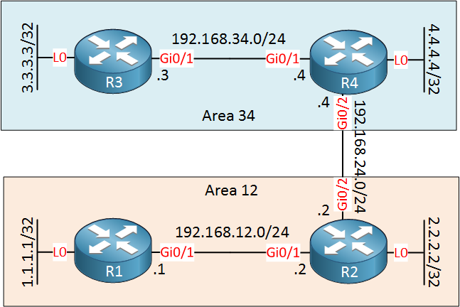
Above we have four routers. R1 and R2 are in area 12, R3 and R4 in area 34. R1 and R3 are intra-area routers so they will be configured as level 1 routers. R2 and R4 form the backbone, so these routers will be configured as level 1-2 routers.
Area 12
Let’s start with area 12. Instead of just showing you the configuration commands, we will also take a look at the different databases so you can see what is going on.
Level-1 Routers
Let’s start with R1. First, we have to start the IS-IS process and set a NET (Network Entity Title). We will keep it simple, the AFI will be 49, and the system ID will be 0000.0000.000X where X is the router number. Here’s R1:
R1(config)#router isis
R1(config-router)#net 49.0012.0000.0000.0001.00
R1 is an intra-area router, so we will configure it as a level-1 router. The default is level 1-2 on Cisco IOS routers, so this is something we have to change:
R1(config-router)#is-type level-1By default, IS-IS will not show when a neighbor adjacency goes up or down on the console. I like to see this so let’s enable it:
R1(config-router)#log-adjacency-changesThe only thing left to do is to enable IS-IS on the interfaces:
R1(config)#interface GigabitEthernet 0/1
R1(config-if)#ip router isis

R1(config)#interface Loopback 0
R1(config-if)#ip router isis
Before we continue with R2, let’s take a look at the database of R1:
R1#show isis database

IS-IS Level-1 Link State Database:
LSPID                 LSP Seq Num  LSP Checksum  LSP Holdtime      ATT/P/OL
R1.00-00            * 0x00000004   0x4240        907               0/0/0
Above we see a single LSP (Link State Packet). This is the LSP that R1 has generated when we enabled IS-IS. You can see a sequence number, checksum, and holdtime. Let’s take a look at the contents of this LSP:
R1#show isis database verbose

IS-IS Level-1 Link State Database:
LSPID                 LSP Seq Num  LSP Checksum  LSP Holdtime      ATT/P/OL
R1.00-00            * 0x00000004   0x4240        870               0/0/0
  Area Address: 49.0012
  NLPID:        0xCC
  Hostname: R1
  IP Address:   1.1.1.1
  Metric: 10         IP 192.168.12.0 255.255.255.0
  Metric: 10         IP 1.1.1.1 255.255.255.255
Above we see the contents of the LSP. There are two prefixes with the metrics and subnet masks.
Let’s continue with R2. This router will be a level 1-2 router since it’s connected to a different area. I’d like to show you the differences between a level 1 and level 1-2 router, so before we use R2 as a level 1-2 router, I’m going to configure it as a level-1 router first:
R2(config)#router isis
R2(config-router)#net 49.0012.0000.0000.0002.00
R2(config-router)#is-type level-1
R2(config-router)#log-adjacency-changes
Don’t forget to enable the interfaces:
R2(config)#interface GigabitEthernet 0/1
R2(config-if)#ip router isis

R2(config)#interface Loopback 0
R2(config-if)#ip router isis
A few seconds later, you will see the neighbor adjacency appearing. This only shows up on the console because of the log-adjacency-changes command:
R1#
%CLNS-5-ADJCHANGE: ISIS: Adjacency to 0000.0000.0002 (GigabitEthernet0/1) Up, new adjacency
R2#
%CLNS-5-ADJCHANGE: ISIS: Adjacency to 0000.0000.0001 (GigabitEthernet0/1) Up, new adjacencyExcellent, we now have two neighbors. You can also verify this with the show isis neighbors command:
R1#show isis neighbors

System Id       Type Interface     IP Address      State Holdtime Circuit Id
R2 L1 Gi0/1 192.168.12.2 UP 9 R2.01R2#show isis neighbors
System Id Type Interface IP Address State Holdtime Circuit Id
R1 L1 Gi0/1 192.168.12.1 UP 22 R2.01Let’s take another look at the database of R1:
R1#show isis database verbose

IS-IS Level-1 Link State Database:
LSPID                 LSP Seq Num  LSP Checksum  LSP Holdtime      ATT/P/OL
R1.00-00            * 0x00000002   0x6DFB        1115              0/0/0
  Area Address: 49.0012
  NLPID:        0xCC
  Hostname: R1
  Metric: 10         IS R2.01
  IP Address:   1.1.1.1
  Metric: 10         IP 1.1.1.1 255.255.255.255
  Metric: 10         IP 192.168.12.0 255.255.255.0
R2.00-00              0x00000002   0xA0BE        1113              0/0/0
  Area Address: 49.0012
  NLPID:        0xCC
  Hostname: R2
  Metric: 10         IS R2.01
  IP Address:   2.2.2.2
  Metric: 10         IP 2.2.2.2 255.255.255.255
  Metric: 10         IP 192.168.12.0 255.255.255.0
R2.01-00              0x00000001   0x7CD6        1113              0/0/0
  Metric: 0          IS R2.00
  Metric: 0          IS R1.00
Above we now also see the LSP from R2 in the database of R1. We can see two prefixes with the metrics and subnet masks.
Network 2.2.2.2/32 was unknown to R1, so this will be installed in the routing table:
R1#show ip route isis

Gateway of last resort is not set

      2.0.0.0/32 is subnetted, 1 subnets
i L1     2.2.2.2 [115/20] via 192.168.12.2, 00:03:18, GigabitEthernet0/1
Above we see 2.2.2.2/32 in the routing table of R1. The administrative distance of IS-IS is 115, and the total metric is 20. You can see that the level (L1) also shows up in the routing table. Let’s take a look at the database of R2:
R2#show isis database verbose

IS-IS Level-1 Link State Database:
LSPID                 LSP Seq Num  LSP Checksum  LSP Holdtime      ATT/P/OL
R1.00-00              0x00000002   0x6DFB        1014              0/0/0
  Area Address: 49.0012
  NLPID:        0xCC
  Hostname: R1
  Metric: 10         IS R2.01
  IP Address:   1.1.1.1
  Metric: 10         IP 1.1.1.1 255.255.255.255
  Metric: 10         IP 192.168.12.0 255.255.255.0
R2.00-00            * 0x00000002   0xA0BE        1017              0/0/0
  Area Address: 49.0012
  NLPID:        0xCC
  Hostname: R2
  Metric: 10         IS R2.01
  IP Address:   2.2.2.2
  Metric: 10         IP 2.2.2.2 255.255.255.255
  Metric: 10         IP 192.168.12.0 255.255.255.0
R2.01-00            * 0x00000001   0x7CD6        1017              0/0/0
  Metric: 0          IS R2.00
  Metric: 0          IS R1.00
Above we see the LSP of R1 with its two prefixes: 1.1.1.1/32 and 192.168.12.0/24. 1.1.1.1/32 was unknown to R2, so this will be installed in the routing table:
R2#show ip route isis

      1.0.0.0/32 is subnetted, 1 subnets
i L1     1.1.1.1 [115/20] via 192.168.12.1, 00:03:16, GigabitEthernet0/1
There it is.
Configurations
Want to take a look for yourself? Here you will find the configuration of R1 and R2 as level 1 routers.
R1
hostname R1
!
ip cef
!
interface Loopback0
 ip address 1.1.1.1 255.255.255.255
 ip router isis
!
interface GigabitEthernet0/1
 ip address 192.168.12.1 255.255.255.0
 ip router isis
!
router isis
 net 49.0012.0000.0000.0001.00
 is-type level-1
 log-adjacency-changes
!
end
R2
hostname R2
!
ip cef
!
interface Loopback0
 ip address 2.2.2.2 255.255.255.255
 ip router isis
!
interface GigabitEthernet0/1
 ip address 192.168.12.2 255.255.255.0
 ip router isis
!
interface GigabitEthernet0/2
 ip address 192.168.24.2 255.255.255.0
!
router isis
 net 49.0012.0000.0000.0002.00
 is-type level-1
 log-adjacency-changes
!
end
Level 1-2 Router
R2 is supposed to connect to area 34 so it has to become a level 1-2 router. I’d like to show you the differences in the database when we change R2 from level 1 to level 1-2. To do this, I will shut the interface that connects to R1 and we will clear the IS-IS neighbor adjacency:
R2(config)#interface GigabitEthernet 0/1
R2(config-if)#shutdown
Clearing the process manually will speed things up. Otherwise, you have to wait until the hold time has expired:
R2#clear isis *Let’s change the level:
R2(config)#router isis
config-router)#is-type ?
  level-1       Act as a station router only
  level-1-2     Act as both a station router and an area router
  level-2-only  Act as an area router only
Let’s go for level 1-2:
R2(config-router)#is-type level-1-2 Let’s take a look at the databases:
R2#show isis database

IS-IS Level-1 Link State Database:
LSPID                 LSP Seq Num  LSP Checksum  LSP Holdtime      ATT/P/OL
R2.00-00            * 0x00000002   0x96EE        1187              0/0/0
IS-IS Level-2 Link State Database:
LSPID                 LSP Seq Num  LSP Checksum  LSP Holdtime      ATT/P/OL
R2.00-00            * 0x00000001   0x98ED        1187              0/0/0
The first thing we see is that R2 now creates two databases; one for level 1 and another for level 2. Let’s take a look at the level 1 database:
R2#show isis database level-1 verbose

IS-IS Level-1 Link State Database:
LSPID                 LSP Seq Num  LSP Checksum  LSP Holdtime      ATT/P/OL
R2.00-00            * 0x00000002   0x96EE        1170              0/0/0
  Area Address: 49.0012
  NLPID:        0xCC
  Hostname: R2
  IP Address:   2.2.2.2
  Metric: 10         IP 2.2.2.2 255.255.255.255
Above we see the LSP that R2 created for level 1. There is only one prefix (2.2.2.2/32) because I shut the GigabitEthernet 0/1 interface. Let’s check the level 2 database:
R2#show isis database level-2 verbose

IS-IS Level-2 Link State Database:
LSPID                 LSP Seq Num  LSP Checksum  LSP Holdtime      ATT/P/OL
R2.00-00            * 0x00000001   0x98ED        1167              0/0/0
  Area Address: 49.0012
  NLPID:        0xCC
  Hostname: R2
  IP Address:   2.2.2.2
  Metric: 10         IP 2.2.2.2 255.255.255.255
The level 2 database is the same, R2 generated an LSP with the 2.2.2.2/32 prefix in it. Let’s enable the GigabitEthernet 0/1 interface so that R1 and R2 form a level 1 neighbor adjacency:
R2(config)#interface GigabitEthernet 0/1
R2(config-if)#no shutdown
Wait for a few seconds until the neighbor adjacency is established, then check the level 2 database:
R2#show isis database level-2 verbose

IS-IS Level-2 Link State Database:
LSPID                 LSP Seq Num  LSP Checksum  LSP Holdtime      ATT/P/OL
R2.00-00            * 0x00000005   0xAB24        1122              0/0/0
  Area Address: 49.0012
  NLPID:        0xCC
  Hostname: R2
  IP Address:   2.2.2.2
  Metric: 10         IP 2.2.2.2 255.255.255.255
  Metric: 10         IP 192.168.12.0 255.255.255.0
  Metric: 20         IP 1.1.1.1 255.255.255.255
Above we now see that R2 has added 1.1.1.1/32 in its own LSP in the level 2 database. R2 learns about 1.1.1.1/32 from R1’s level 1 LSP and adds this prefix in its own level 2 database.
When we now look at the routing table of R1, you will only see the 2.2.2.2/32 prefix:
R1#show ip route isis

      2.0.0.0/32 is subnetted, 1 subnets
i L1     2.2.2.2 [115/20] via 192.168.12.2, 00:23:02, GigabitEthernet0/1
Once R2 is connected to another area, you will find a default route here.
Area 34
Let’s continue with our configuration. First, we will configure R3 and R4 so that they form a level 1 neighbor adjacency. Let’s start with R3:
R3(config)#router isis
R3(config-router)#net 49.0034.0000.0000.0003.00
R3(config-router)#is-type level-1
R3(config-router)#log-adjacency-changes
Don’t forget to enable IS-IS on the interfaces:
R3(config)#interface GigabitEthernet 0/1
R3(config-if)#ip router isis

R3(config)#interface Loopback 0
R3(config-if)#ip router isis
And here’s R4:
R4(config)#router isis
R4(config-router)#net 49.0034.0000.0000.0004.00
R4(config-router)#log-adjacency-changes
Add the interfaces:
R4(config)#interface GigabitEthernet 0/1
R4(config-if)#ip router isis

R4(config)#interface Loopback 0
R4(config-if)#ip router isis
Let’s verify that R3 and R4 are neighbors:
R3#show isis neighbors

System Id       Type Interface     IP Address      State Holdtime Circuit Id
R4              L1   Gi0/1         192.168.34.4    UP    8        R4.01
This is looking good.
Area 12-34 connectivity
Now it’s time to connect area 12 and area 34 to each other. Before we do, let’s take a quick look at the level 2 databases of R2 and R4 so that you can see the difference later:
R2#show isis database level-2 verbose

IS-IS Level-2 Link State Database:
LSPID                 LSP Seq Num  LSP Checksum  LSP Holdtime      ATT/P/OL
R2.00-00            * 0x00000009   0xA328        1189              0/0/0
  Area Address: 49.0012
  NLPID:        0xCC
  Hostname: R2
  IP Address:   2.2.2.2
  Metric: 10         IP 2.2.2.2 255.255.255.255
  Metric: 10         IP 192.168.12.0 255.255.255.0
  Metric: 20         IP 1.1.1.1 255.255.255.255
Above we see that R2 has its own directly connected interfaces (2.2.2.2/32 and 192.168.12.0/24) and the prefix from R1 (1.1.1.1/32) in its LSP. Here’s R4:
R4#show isis database level-2 verbose

IS-IS Level-2 Link State Database:
LSPID                 LSP Seq Num  LSP Checksum  LSP Holdtime      ATT/P/OL
R4.00-00            * 0x00000004   0x87F4        868               0/0/0
  Area Address: 49.0034
  NLPID:        0xCC
  Hostname: R4
  IP Address:   4.4.4.4
  Metric: 10         IP 192.168.34.0 255.255.255.0
  Metric: 10         IP 4.4.4.4 255.255.255.255
  Metric: 20         IP 3.3.3.3 255.255.255.255
R4 has its directly connected interfaces (192.168.34.0/24 and 4.4.4.4/32) and the prefix from R3 (3.3.3.3/32) in its LSP.
Let’s configure R2 and R4 to run IS-IS on the interfaces that connect them:
R2 & R4
(config)#interface GigabitEthernet 0/2
(config-if)#ip router isis
A few seconds later, a level 2 neighbor adjacency is established:
R2#
%CLNS-5-ADJCHANGE: ISIS: Adjacency to 0000.0000.0004 (GigabitEthernet0/2) Up, new adjacency
R4#
%CLNS-5-ADJCHANGE: ISIS: Adjacency to 0000.0000.0002 (GigabitEthernet0/2) Up, new adjacencyLet’s see what the level 2 databases now look like. We start with R2:
R2#show isis database level-2 verbose

IS-IS Level-2 Link State Database:
LSPID                 LSP Seq Num  LSP Checksum  LSP Holdtime      ATT/P/OL
R2.00-00            * 0x0000000B   0x5D37        1146              0/0/0
  Area Address: 49.0012
  NLPID:        0xCC
  Hostname: R2
  Metric: 10         IS R2.02
  IP Address:   2.2.2.2
  Metric: 10         IP 2.2.2.2 255.255.255.255
  Metric: 10         IP 192.168.12.0 255.255.255.0
  Metric: 20         IP 1.1.1.1 255.255.255.255
  Metric: 10         IP 192.168.24.0 255.255.255.0
R2.02-00            * 0x00000001   0x5283        1147              0/0/0
  Metric: 0          IS R2.00
  Metric: 0          IS R4.00
R4.00-00              0x00000006   0xC77D        1149              0/0/0
  Area Address: 49.0034
  NLPID:        0xCC
  Hostname: R4
  Metric: 10         IS R2.02
  IP Address:   4.4.4.4
  Metric: 10         IP 192.168.34.0 255.255.255.0
  Metric: 10         IP 4.4.4.4 255.255.255.255
  Metric: 20         IP 3.3.3.3 255.255.255.255
  Metric: 10         IP 192.168.24.0 255.255.255.0
Above we see that R2 has added 192.168.24.0/24 to its own LSP. R2 also has received the LSP from R4 and added this to its level 2 database. Let’s check its routing table:
R2#show ip route isis

      1.0.0.0/32 is subnetted, 1 subnets
i L1     1.1.1.1 [115/20] via 192.168.12.1, 00:33:59, GigabitEthernet0/1
      3.0.0.0/32 is subnetted, 1 subnets
i L2     3.3.3.3 [115/30] via 192.168.24.4, 00:01:35, GigabitEthernet0/2
      4.0.0.0/32 is subnetted, 1 subnets
i L2     4.4.4.4 [115/20] via 192.168.24.4, 00:01:35, GigabitEthernet0/2
i L2  192.168.34.0/24 [115/20] via 192.168.24.4, 00:01:35, GigabitEthernet0/2
We can now see that R2 has added the level 2 prefixes that it has learned in the routing table. Let’s check R4:
R4#show isis database level-2 verbose

IS-IS Level-2 Link State Database:
LSPID                 LSP Seq Num  LSP Checksum  LSP Holdtime      ATT/P/OL
R2.00-00              0x0000000B   0x5D37        1136              0/0/0
  Area Address: 49.0012
  NLPID:        0xCC
  Hostname: R2
  Metric: 10         IS R2.02
  IP Address:   2.2.2.2
  Metric: 10         IP 2.2.2.2 255.255.255.255
  Metric: 10         IP 192.168.12.0 255.255.255.0
  Metric: 20         IP 1.1.1.1 255.255.255.255
  Metric: 10         IP 192.168.24.0 255.255.255.0
R2.02-00              0x00000001   0x5283        1137              0/0/0
  Metric: 0          IS R2.00
  Metric: 0          IS R4.00
R4.00-00            * 0x00000006   0xC77D        1143              0/0/0
  Area Address: 49.0034
  NLPID:        0xCC
  Hostname: R4
  Metric: 10         IS R2.02
  IP Address:   4.4.4.4
  Metric: 10         IP 192.168.34.0 255.255.255.0
  Metric: 10         IP 4.4.4.4 255.255.255.255
  Metric: 20         IP 3.3.3.3 255.255.255.255
  Metric: 10         IP 192.168.24.0 255.255.255.0
R4 receives the level 2 LSP from R2 with all its prefixes. It also adds 192.168.24.0/24 to its own LSP since IS-IS was activated on this interface. Let’s check its routing table:
R4#show ip route isis

      1.0.0.0/32 is subnetted, 1 subnets
i L2     1.1.1.1 [115/30] via 192.168.24.2, 00:02:00, GigabitEthernet0/2
      2.0.0.0/32 is subnetted, 1 subnets
i L2     2.2.2.2 [115/20] via 192.168.24.2, 00:02:00, GigabitEthernet0/2
      3.0.0.0/32 is subnetted, 1 subnets
i L1     3.3.3.3 [115/20] via 192.168.34.3, 00:08:19, GigabitEthernet0/1
i L2  192.168.12.0/24 [115/20] via 192.168.24.2, 00:02:00, GigabitEthernet0/2
We see that R4 has added these new prefixes to its routing table. They show up as level 2 routes.
What about the intra-area routers, R1 and R3? Once R2 and R4 got connected to another area, they set the attached bit in their level 1 LSPs. When the intra-area routers receive this, they generate a default router that points to the level 1-2 router. Let’s check R1:
R1#show ip route isis

Gateway of last resort is 192.168.12.2 to network 0.0.0.0

i*L1  0.0.0.0/0 [115/10] via 192.168.12.2, 00:03:02, GigabitEthernet0/1
      2.0.0.0/32 is subnetted, 1 subnets
i L1     2.2.2.2 [115/20] via 192.168.12.2, 00:35:24, GigabitEthernet0/1
i L1  192.168.24.0/24 [115/20] via 192.168.12.2, 00:03:31, GigabitEthernet0/1
We now see a default route in R1’s routing table that points to R2. The same thing applies to R3:
R3#show ip route isis

i*L1  0.0.0.0/0 [115/10] via 192.168.34.4, 00:03:47, GigabitEthernet0/1
      4.0.0.0/32 is subnetted, 1 subnets
i L1     4.4.4.4 [115/20] via 192.168.34.4, 00:10:13, GigabitEthernet0/1
i L1  192.168.24.0/24 [115/20] via 192.168.34.4, 00:03:57, GigabitEthernet0/1
R3 has a default route that points to R4. Everything is looking good but just in case and to get a bit of satisfaction, let’s try a quick ping between R1 and R3:
Hi Rene, If there is multiple Level1-2 Router on a area then due to default Route asymmetric Routing will be occurred. I saw your topic about Route leaking but I think its not scalable more . So is there any other scaleble option here ??
Thx for your very nice article as always
Hi @Zaman.rubd,
Since IS-IS routers only have a default route to get to other areas, sub-optimal routing can be an issue yes. It will depend on your network design. There’s not really an alternative to route leaking as far as I know…somehow you have to get those more specific prefixes in the routing table of your L1 routers.
For anyone else that is reading this and wondering what this is about, here is an example for IS-IS route leaking and sub-optimal routing:
https://networklessons.com/cisco/ccie-routing-switching-written/is-is-route-leaking
Hello René,
Thank you a lot for this lesson. But I don’t see this command circuit-type level anywhere in the course. Normal?
Hello Djan,
I haven’t added this command indeed. It is pretty straight-forward though, you can use it to tell the router which hello packets to send on the interface: L1, L2 or L1 and L2. You can do this per interface so on Gi0/1 you could send L1 hello packets and on Gi0/2 only L2 hello packets.
Rene
Hello Eduardo
Since the default is-type is level 1-2, then you don’t actually have to explicitly configure the router as a level 1-2 router. This command can indeed be deleted. However, as is the case with many such commands, it’s a good idea to verify that the configuration is correct by implementing the command. This is all the more important when you configure devices that have been previously configured and may have some other configuration already set up.
I hope this has been helpful!
Laz