Lesson Contents
IS-IS is an IGP, link-state routing protocol, similar to OSPF. It forms neighbor adjacencies, has areas, exchanges link-state packets, builds a link-state database and runs the Dijkstra SPF algorithm to find the best path to each destination, which is installed in the routing table.
Back when OSPF and IS-IS were developed, IP wasn’t the dominant protocol that it is today. When people think of OSI they automatically think of the OSI-model but back then, ISO (International Organization for Standardization) also created something similar to IP and UDP called CLNP (Connectionless-mode Network Protocol) and CLNS (Connectionless-mode Network Service).
ISO also uses some different terminology, for example:
- Router = Intermediate system
- Host = End system
Unlike OSPF which was developed by the IETF (Internet Engineering Task Force), IS-IS was originally developed by DEC for CLNS, not IP and this is why it’s called IS-IS (Intermediate System – Intermediate System).
Later, IS-IS was adapted so that it could also route IP and is then called integrated IS-IS.
Nowadays, we use IP everywhere so you might wonder why we care about this. When working with IS-IS, you will see some references to CLNP/CLNS here and there. For example, when configuring a router ID (called a Network Entity Title), it has to be configured with the NSAP (Network Service Access Point Address) format. NSAP is similar to an IP address, and it is not automatically configured so we have to understand its format.
IS-IS also rides directly on top of an Ethernet header, using its own header format. It’s not encapsulated in an IP packet like other routing protocols (OSPF and EIGRP) are:

IS-IS is a highly scalable routing protocol, which is why it is used often on large service provider network backbones. In this lesson I will give you an overview of what IS-IS is and how it works.
Areas and Router Roles
IS-IS uses different areas where the entire router sits in an area, not just one of its interfaces like with OSPF. There is no backbone area, the backbone is formed by a string of routers.
There are three types of routers:
- Level 1 system: this is an intra-area router, it only knows what the local area looks like and will only learn prefixes from its own area. It creates a level 1 link-state database and SPF tree for the area.
- Level 2 system: this is a backbone router that knows all intra-area and inter-area routes. It creates a level 2 link-state database and SPF tree for the backbone.
- Level 1-2 system: this is a router that performs both roles. It creates a separate level 1 and 2 link-state database and two SPF trees, one for each database.
Similar to other routing protocols like OSPF and EIGRP, IS-IS routers will send hello packets. When you send and receive hello packets, you will form a neighbor adjacency. Routers will only form neighbor adjacencies with routers that use the same level.
Let’s look at some examples to help you visualize this. Let’s start with a single area:
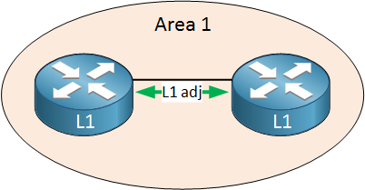
Above we have two routers in a single area. There is only one area so these two routers are configured as level 1 routers. These two routers will form a level 1 neighbor adjacency. Let’s add a second area:
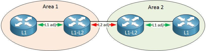
Level 1 routers only know what the local area looks like. If a level 1 router wants to reach something outside of its area, it has to use a level 2 router. In each area, we configure one router as a level 1-2 router.
These level 1-2 routers will establish two neighbor adjacencies:
- Level 1 neighbor adjacency with the router in the same area.
- Level 2 neighbor adjacency with the router in the other area.
Here is one more example, a larger topology that gives a good overview of the different router levels and adjacencies:
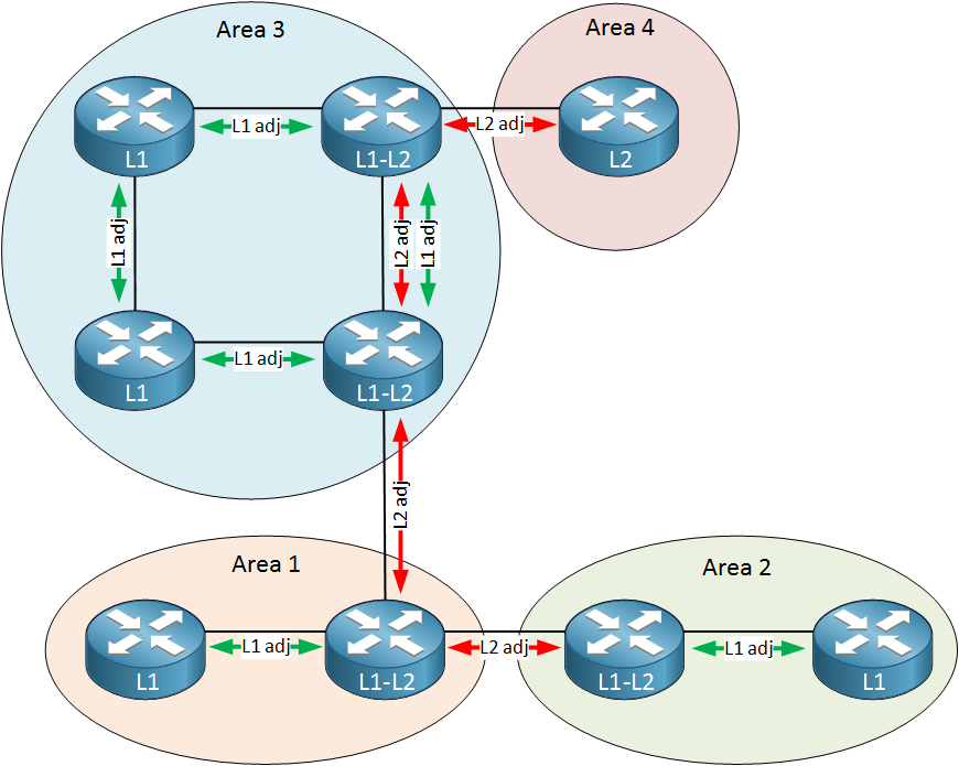
Above you see two interesting things:
- The router in area 4 is a level 2 backbone router. There are no level 1 routers in area 4 so we don’t need a level 1-2 router there.
- Area 3 has two level 1-2 routers. These routers will form two neighbor adjacencies with each other:
- Level 1 adjacency
- Level 2 adjacency
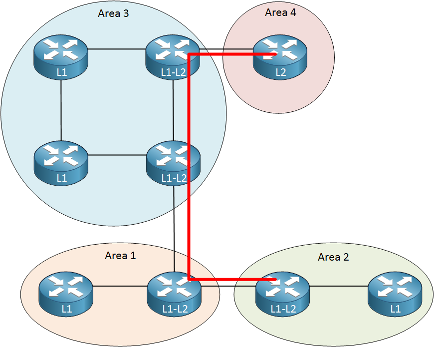
The level two routers form a continuous string of backbone routers:
LSPs (Link State Packets)
Let’s talk about how IS-IS exchanges routing information. It uses LSPs (Link State Packet) which is similar to OSPF’s LSAs. In the LSP you will find:
- One or more prefixes
- Adjacent neighbors
- Metric
Let’s take a closer look at how IS-IS uses LSPs to exchange routing information. Let’s start with two routers that are configured to use IS-IS but there is no neighbor adjacency yet:
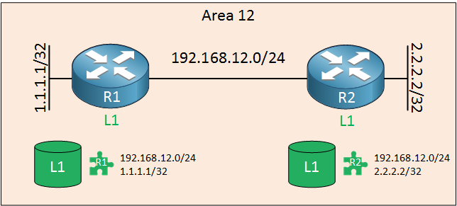
Each router will create an LSP (illustrated with the green jigsaw) . In the LSP we find the directly connected networks that are advertised in IS-IS. A few seconds later, these routes become neighbors:
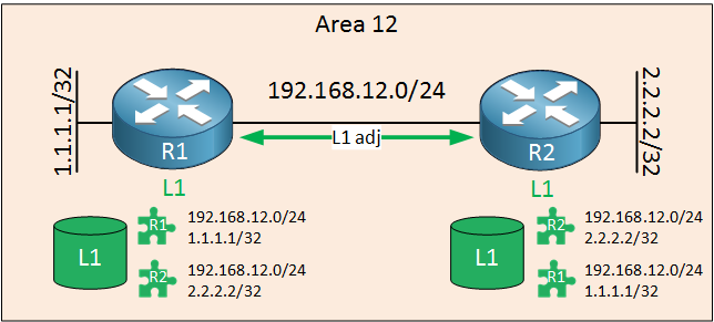
R1 and R2 are in the same area so they will establish a level 1 neighbor adjacency. These routers will flood their LSPs within the area so that everyone knows about all LSPs in the area. The two routers add each others LSP in their database. These routers can now run SPF on their level 1 database and figure out the shortest path to each destination.
Let’s say we want to connect area 12 to another area, this means we need a level 2 router. Let’s convert R2 into a level 1-2 router so I can show you what will happen. At this moment, we start with a clean slate so there is no neighbor adjacency between R1 and R2:
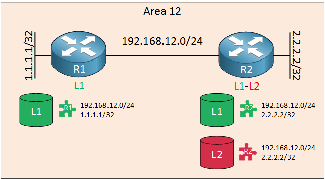
R2 now has a second database, the level 2 database. Besides its level 1 database and level 1 LSP, it now also has a level 2 database. It generates a level 2 LSP and all prefixes for interfaces that are directly connected and advertised in IS-IS.
A few seconds later, R1 and R2 form a level 1 neighbor adjacency:
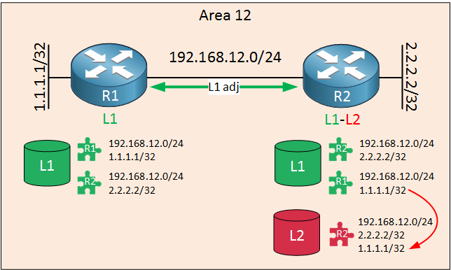
Once again, R1 and R2 will exchange their level 1 LSPs. R2 receives the level 1 LSP from R1 and it copies new prefixes from its level 1 database to the LSP in the level 2 database. In my example, that is 1.1.1.1/32 from R1.
Let’s continue this story. I will add a second area now, similar to area 12. There is no connection yet between the two areas but the routers have formed a level 1 neighbor adjacency within the area:
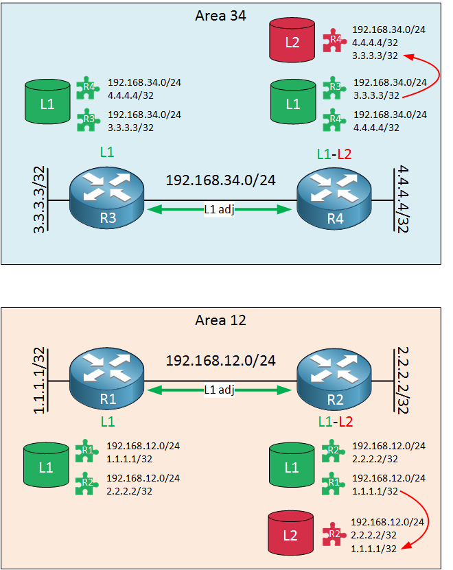
As you can see above, R4 has learned about the 3.3.3.3/32 prefix from R3 and copies this prefix from the LSP in the level 1 database to its own LSP in the level 2 database.
Now we will create a connection between the two areas and enable IS-IS on this link Something exciting will happen:
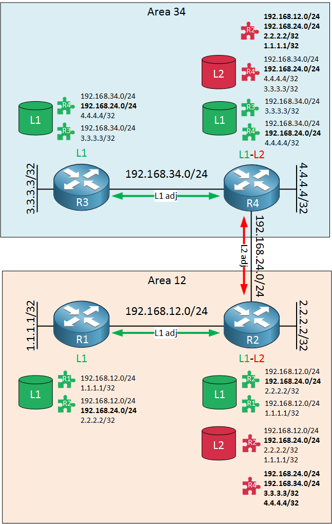
R2 and R4 are in different areas and will establish a level 2 neighbor adjacency. There are a couple of things that will happen:
- The 192.168.24.0/24 prefix is added in the level 1 LSP of R2 and R1 learns about it.
- The 192.168.24.0/24 prefix is added in the level 2 LSP of R2.
- The 192.168.24.0/24 prefix is added in the level 1 LSP of R4 and R3 learns about it.
- The 192.168.24.0/24 prefix is added in the level 2 LSP of R4.
- The level 2 LSPs are flooded within the backbone, R2 and R4 will receive each others level 2 LSPs.
- R2 learns about 192.168.24.0/24, 192.168.34.0/24, 3.3.3.3/32 and 4.4.4.4/32 from R4.
- R4 learns about 192.168.24.0/24, 192.168.12.0/24, 1.1.1.1/32 and 2.2.2.2/32 from R2.
The two backbone routers R2 and R4 now know about every prefix out there.
If you look at the level 1 database of R1 and R3, you can see they don’t learn about prefixes from the other area. This is how IS-IS works, a level 1 router will never learn about prefixes from other areas. So, how do we get out of our own area?
Once a level 1-2 router is connected to another area, it will set a special bit in its level 1 LSP called the attached bit. When a level 1 router sees this, it will generate a default route that is pointed to the level 1-2 router.
Since IS-IS is a link-state routing protocol, it is important that the databases are synchronized. Each LSP has a sequence number that is increased whenever there is a change in the LSP. LSPs are acknowledged using an SNP (Sequence Number Packet) that comes in two flavors:
- CSNP (Complete SNP)
- PSNP (Partial SNP)
The CSNP has a list of all LSPs in the database, it is used to inform other routers that have missing or outdated information. The PSNP is used to request one or more LSPs and also used to acknowledge the receipt of one or more LSPs.
NET (Network Entity Title)
The NET (Network Entity Title) is the unique identifier for each IS-IS router. Most routing protocols use the highest IP address as a router/system ID but alas, IS-IS was not developed with IP in mind. The NET is based on an NSAP address and has to be configured manually so we have to understand it.
Here’s what it looks like:
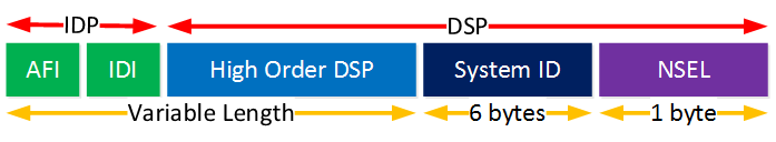
The NET consists of two “major” parts and can be anywhere between 8 and 20 bytes:
- IDP (Initial Domain Part)
- DSP (Domain Specific Part)
The IDP is used to tell to which routing domain you belong and has two parts:
- AFI (Authority and Format Identifier): The AFI identifies the administrative authority that is responsible for assigning you addressing. The AFI coding is administered by ISO.
- IDI (Initial Domain Identifier): The IDI depends on the authority. They will typically use a different value for each customer that refers to a (sub) domain number.
It’s very unlikely that you will ever see this as IS-IS is pretty much used only on private networks. A possible scenario could be where a customer runs IS-IS with a service provider, where the provider assigns the IDP to a customer.
On private networks, you have two options:
- Use AFI 49 which is reserved for private networks. If you use this, the IDI is optional.
- Don’t use the IDP at all.
The second part of the NET is the DSP, these are your “local” settings:
- High Order DSP: this is where we enter the area number.
- System ID: this is a unique ID for each router. You can enter whatever you want as long as it’s unique within the area.
- NSEL: the NSEL is similar to a port or socket in IP/TCP. This always has to be a value of 0, which indicates the router itself.
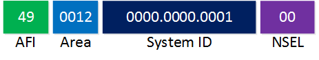
Let’s look at some examples. The first NET is an example where an authority has assigned you an IDP:
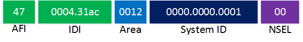
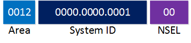
The area number is 12 and the unique ID of this router is 0000.0000.0001. This could be an example for R1. If you use a private network, you can set the AFI to 49 and forget about the IDI:
This is the most common example. This is for a router in area 12 with system ID 0000.0000.0001. One last example, you can remove the IDP completely if you want:
This only leaves the area number, system ID and the NSEL. Let me show you one example of the previous four routers I used and the NETs we could use for them:
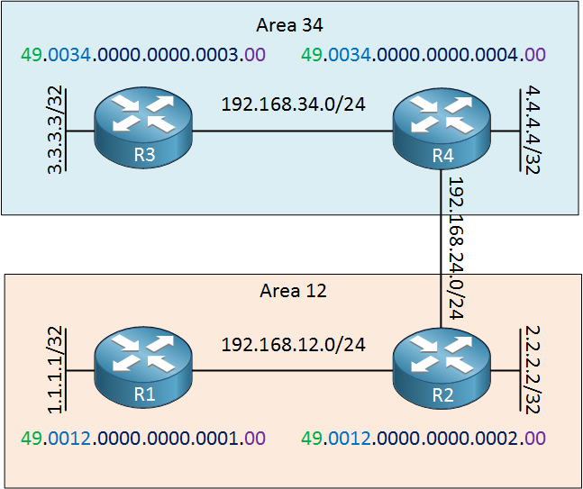
Above you can see that all routers use AF 49. R1 and R2 use 0012 to indicate their area number, R3 and R4 use 0034 as the area number. Here are the system IDs:
- R1: 0000.0000.0001
- R2: 0000.0000.0002
- R3: 0000.0000.0003
- R4: 0000.0000.0004
The NSEL has to be set to 0 on all routers.
Metrics
IS-IS has four metric values that it can work with:
- Default Metric: every interface has a default metric of 10, no matter the bandwidth. A gigabit interface gets the same metric as a serial link. We can manually configure a different metric for each interface.
- Delay: similar to how EIGRP uses delay.
- Expense: the actual monetary cost of a link.
- Error: similar to how EIGRP uses reliability.
Cisco IOS routers, however, only support the default metric so that’s one one thing less to worry about.
Dear Rene,
Great stuff to read.
Can you please bit more elaborate CSNP and PSNP with examples its good if you capture it in Wireshare as well.
Thanks
Waqar
Hi Rene,
I have little bit confusion about CLNP (Connectionless-mode Network Protocol) and CLNS (Connectionless-mode Network Service). Could you please help me to understand it more easily ? Thx
br//zaman
Hello Mohammad.
Think about the CSNP as a packet that contains all of the LSPs from the current database. If this packet is sent to another router, the recipient will have a complete list of LSPs, in other words, it will have the sending router’s current view of the network. These packets are similar to OSPF database description packets.
The PSNP is a partial list of LSPs. This is sent as a response to a specific request for specific information (for specific prefixes). This can be used to request an LSP (or LSPs) and also to acknowledge the recipt of an LS
... Continue reading in our forumHello Mohammad Zaman
CLNS is the OSI based service that provides connectionless network services, that is, connectivity between nodes. It essentially provides capabilities in an OSI network environment similar to those provided by IP and UDP together. UDP is mentioned here and not TCP because CLNS is strictly a best-effort service. CLNP is the actual protocol that is used to implement it.
ISO (the governing body that defines these standards) makes a distiction between the service offered to higher layers (CLNS) and the protocol used to implement it (CLNP).
... Continue reading in our forumHi Laz,
Thanks for this informative feedback.
Intermediate system ( Level 1 or Level 2 ) generate only one LSP per level and that LSP contain all prefixes that ISIS is originating.
-If one LSP is carrying all prefixes,how CSNP comes into play.
-Is PSNP behaviour is same for Broadcast and Point to Point network types.
Thanks
//BR
Mohammed Waqar