The Cisco 1941W router has wireless onboard, but this isn’t just any ordinary “wireless” interface. It’s a complete access point that has to be configured separately from the router. The router and (virtual) access point are connected to each other by using a virtual gigabit interface. Let me give you a picture to help you visualize how this works internally:
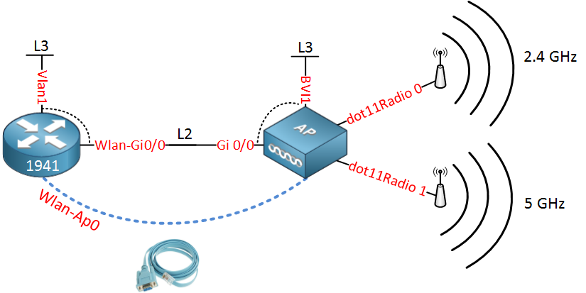
All the interfaces above are not real but virtual interfaces on the router. Let me explain each interface to you:
- The router has a Wlan-AP0 interface which is only used to access the console of the access point.
- The access point has a dot11Radio 0 interface which is the radio for the 2.4GHz frequency.
- The access point also has a dot11Radio 1 interface which is the radio for the 5GHz frequency.
- The access point has a Gi0/0 interface which is connected to the Wlan-Gi0/0 on the router.
- The Wlan-Gi0/0 on the router and the Gi 0/0 interface on the access point are layer 2 interfaces (switchport) that we can use as a trunk.
- The Vlan1 interface on the router is a routed port where you can configure an IP address. It’s connected to the Wlan-Gi0/0 interface, so that’s why you see the dashed line.
- The BVI1 interface on the access point is similar to the Vlan1 interface of the router. It’s connected to the Gi0/0 interface.
The logic behind these interfaces is that each SSID you configure for the wireless network will be assigned to a single VLAN. The virtual Gigabit link between the access point and router can be configured as a trunk so that all (wireless) traffic can be isolated in VLANs.
Each VLAN will need an IP address that can be used as the default gateway for its wireless clients. That’s why we need to create VLAN interfaces on the router.
In the next part of this lesson, I’ll give you a configuration example where we will create a wireless network and two VLANs:
- One VLAN for wireless users.
- One VLAN for management traffic.
Just like a router or switch, we can connect to the virtual access point through SSH for remote management. Also, if you are using WPA-2 enterprise, the access point will communicate with an external radius server. We need to make sure that management traffic doesn’t get mixed up with wireless traffic, so that’s why we need to create at least two VLANs. Our network will look like this:
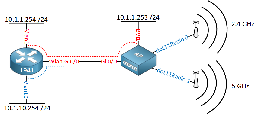
Let me explain this picture:
- On the router, we will configure IP address 10.1.1.254 on the Vlan 1 interface, and on the access point, we have 10.1.1.253 on its BVI1 interface. This will be used for management traffic.
- The Vlan10 interface on the router will have IP address 10.1.10.254, this will be the default gateway for the wireless users.
Let’s take a look at the configuration!
First, we will configure a DHCP pool for the wireless users:
Router(config)#ip dhcp pool VLAN10-WIFI
Router(dhcp-config)#network 10.1.10.0 255.255.255.0
Router(dhcp-config)#default-router 10.1.10.254
Router(dhcp-config)#dns-server 8.8.8.8
The IP address on the Vlan10 interface will be the default gateway, and we’ll use Google DNS (8.8.8.8).
The next step is to make sure the Wlan-Gi0/0 interface is operational:
Router(config)#interface Wlan-GigabitEthernet0/0
Router(config-if)#no shutdown
Now we will configure the Wlan-Ap0 interface so that we can access the console of the access point:
Router(config)#interface wlan-ap 0
The wlan-ap 0 interface is used for managing the embedded AP.
Please use the "service-module wlan-ap 0 session" command to console into the embedded AP

Router(config-if)#ip address 11.11.11.11 255.255.255.255
Pick whatever IP address you want. Just make sure it’s not already in use on your network. The router only uses this IP address internally for the console connection. Let’s configure the trunk on the router:
Router(config)#interface wlan-gigabitEthernet 0/0
Router(config-if)#switchport mode trunk
Let’s configure the Vlan1 interface for management traffic:
Router(config)#interface vlan 1
Router(config-if)#ip address 10.1.1.254 255.255.255.0
And don’t forget the VLAN for our wireless users:
Router(config)#vlan 10
Router(config-vlan)#name WIFI
Router(config-vlan)#exitRouter(config)#interface vlan 10
Router(config-if)#ip address 10.1.10.254 255.255.255.0The router is now ready. Let’s move over to the access point:
Router#service-module wlan-ap 0 session
Trying 1.1.1.1, 2067 ... Open

ap#
You are now connected to the access point. In case you have to enter a username/password, This is usually cisco/cisco. Let’s erase the default config so we can start with a clean one:
ap#erase startup-config
Erasing the nvram filesystem will remove all configuration files! Continue? [confirm]
[OK]
Erase of nvram: complete
And reload it…
ap#reloadOnce the access point is reloaded, we’ll log in again, the default password for enable is normally ‘Cisco’:
Ap>enable
Password: Cisco
Ap#
Our next move is to configure the gigabit interface of the access point. We will use the BVI interfaces to tell the interface to which VLANs it belongs:
Ap# configure terminal
Ap(config-if)#interface gigabitEthernet 0
Ap(config-subif)#bridge-group 1Ap(config-if)#interface gigabitEthernet 0.10
Ap(config-subif)#encapsulation dot1Q 10
Ap(config-subif)#bridge-group 10Bridge-group 1 is for VLAN 1 and will be untagged. Bridge-group 10 will use a sub-interface and should be tagged as VLAN 10.
Now we’ll configure the BVI interface for management traffic:
Ap(config)#bridge irb
Ap(config)#interface BVI 1
Ap(config-if)#ip address 10.1.1.253 255.255.255.0
We don’t need a BVI interface for VLAN 10 because wireless users only require an IP address on the router as a default gateway. The routing/switching configuration is now complete. Let’s work on the wireless part.
First, we will create a simple wireless network that uses a pre-shared key for WPA:
Nice explaination!!! Thank you!
Rene,
I have a cisco 1941w router that we just bought and I am having a lot of problems trying to get it configured correctly. I went through your post until I got to the Access Point configuration part and it wouldn’t let me use “config t”. Any help would be much appreciated.
Thanks,
Blaine
Hi Blaine,
Did you use “enable” before trying to use “configure terminal” ? The access point is configured the same way as a router, switch or any other IOS device.
Rene
I own this router and I plan on setting it up for home user. Can I create a 3rd ssid for Guest?
What I really want to do is create an SSID for my 2.4GHz (Home2G) and one for my 5GHz radio (Home5G). Then on the 2.4GHz, create a 3rd one for Home2GGuest.
Is this possible?
I guess I can do:
... Continue reading in our forumOne more question. I’m confused about the BVI interface and the Wireless Management interface (Console AP). How come we need two management interfaces for the AP?