In this lesson I’m going to walk you through the configuration of a small MPLS VPN network using MP-BGP (Multi-Protocol Border Gateway Protocol) and only two VRFs. I will be using the following topology for this:
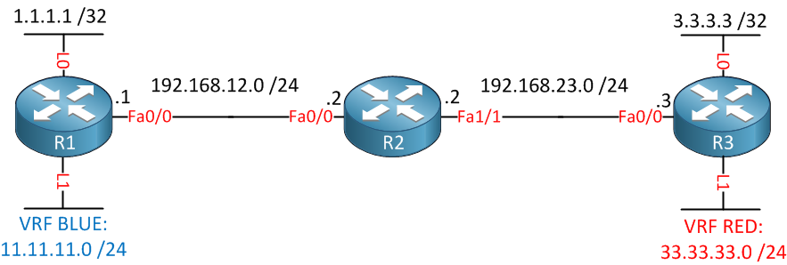
Above you see 3 routers connected to each other. R1 and R3 each have two loopback interfaces. The loopback 0 interface will be used to establish a BGP neighbor adjacency, the loopback 1 interfaces will be in two different VRFs called blue and red.
First we’ll configure OSPF so that R1 and R3 can reach each others loopback 0 interface:
R1(config)#router ospf 1
R1(config-router)#network 192.168.12.1 0.0.0.0 area 0
R1(config-router)#network 1.1.1.1 0.0.0.0 area 0R2(config)#router ospf 1
R2(config-router)#network 192.168.12.2 0.0.0.0 area 0
R2(config-router)#network 192.168.23.2 0.0.0.0 area 0R3(config)#router ospf 1
R3(config-router)#network 192.168.23.3 0.0.0.0 area 0
R3(config-router)#network 3.3.3.3 0.0.0.0 area 0We’ll continue by configuring MPLS on the interfaces of all routers:
R1(config)#interface fastEthernet 0/0
R1(config-if)#mpls ipR2(config)#interface fastEthernet 0/0
R2(config-if)#mpls ip
R2(config)#interface fastEthernet 1/0
R2(config-if)#mpls ipR3(config)#interface fastEthernet 0/0
R3(config-if)#mpls ipEnabling MPLS is simple enough, let’s verify that we have neighbors:
R2#show mpls ldp neighbor
    Peer LDP Ident: 1.1.1.1:0; Local LDP Ident 192.168.23.2:0
	TCP connection: 1.1.1.1.646 - 192.168.23.2.35345
	State: Oper; Msgs sent/rcvd: 7/7; Downstream
	Up time: 00:00:21
	LDP discovery sources:
	  FastEthernet0/0, Src IP addr: 192.168.12.1
        Addresses bound to peer LDP Ident:
          192.168.12.1    1.1.1.1
    Peer LDP Ident: 3.3.3.3:0; Local LDP Ident 192.168.23.2:0
	TCP connection: 3.3.3.3.646 - 192.168.23.2.45741
	State: Oper; Msgs sent/rcvd: 7/7; Downstream
	Up time: 00:00:03
	LDP discovery sources:
	  FastEthernet1/0, Src IP addr: 192.168.23.3
        Addresses bound to peer LDP Ident:
          192.168.23.3    3.3.3.3
Fair enough, R2 has two MPLS LDP neighbors. If you are interested, you can take a look at the labels that are in use:
R1#show mpls forwarding-table
Local  Outgoing    Prefix            Bytes tag  Outgoing   Next Hop
tag    tag or VC   or Tunnel Id      switched   interface
16     17          3.3.3.3/32        0          Fa0/0      192.168.12.2
17 Pop tag 192.168.23.0/24 0 Fa0/0 192.168.12.2R2#show mpls forwarding-table
Local Outgoing Prefix Bytes tag Outgoing Next Hop
tag tag or VC or Tunnel Id switched interface
16 Pop tag 1.1.1.1/32 0 Fa0/0 192.168.12.1
17 Pop tag 3.3.3.3/32 0 Fa1/0 192.168.23.3R3#show mpls forwarding-table
Local Outgoing Prefix Bytes tag Outgoing Next Hop
tag tag or VC or Tunnel Id switched interface
16 Pop tag 192.168.12.0/24 0 Fa0/0 192.168.23.2
17 16 1.1.1.1/32 0 Fa0/0 192.168.23.2With MPLS running and labels being advertised, we can continue and create the two VRFs:
R1(config)#ip vrf BLUE
R1(config-vrf)#rd 100:1
R1(config-vrf)#route-target export 100:1
R1(config-vrf)#route-target import 100:3
VRF Blue will be created on R1. We will use RD (Route Distinguisher) 100:1 for VRF blue and 100:3 for VRF red. Now we can create a new loopback and add it to the VRF:
R1(config)#interface loopback1
R1(config-if)#ip vrf forwarding BLUE
R1(config-if)#ip address 11.11.11.11 255.255.255.0
Loopback 1 has an IP address and is added to VRF blue. Now let’s do the same thing on R3:
R3(config)#ip vrf RED
R3(config-vrf)#rd 100:3
R3(config-vrf)#route-target export 100:3
R3(config-vrf)#route-target import 100:1
R3(config)#interface loopback 1
R3(config-if)#ip vrf forwarding RED
R3(config-if)#ip address 33.33.33.33 255.255.255.0
On R3, we’ll create VRF red and use 100:3 as the RD. Now we can configure BGP on both routers:
what is the use of the above command.if we not provided these commands what will happened. could u explain each and every functionality of above command
BGP by default only carries IPv4 unicast prefixes. MP-BGP (Multiprotocol) lets us send other stuff like IPv6 or VPN routes for MPLS. A VPN route is a prefix + the 64-bit RD (Route distinguisher).
In order to send these VPN routes between BGP neighbors you need to activate the VPNv4 address family.
Extended communities are used for route import/export policies and also to carry OSPF or EIGRP attributes across MP-BGP.
I’ll write some more MPLS lessons in the future to explain it more.
Hi Rene - what about R2, don’t we need to configure VRF on R2 also? how the middle router will come to know about the VRF data, OR the middle one is only a transit router that works on MPLS BGP.
I’ll write some more mpls tutorials in the future, there’s plenty to talk about.
Hi Rene,
Thanks for these amazing tutorials,
When you configured OSPF, you already had reachability between R1 and R3, am I correct ? What is the use of configuring BGP ? When OSPF provided reach ability between these non directly connected networks.
Thanks a lot