Lesson Contents
L2TPv3 (Layer Two Tunneling Protocol Version 3) is a point-to-point layer two over IP tunnel.
This means you can tunnel L2 protocols like Ethernet, Frame-relay, ATM, HDLC, PPP, etc. over an IP network. This can be pretty useful…For example, let’s say you have two remote sites and an application that requires that hosts are on the same subnet. With L2TPv3, it’s no problem to “bridge” two remote sites together, putting them in the same broadcast domain/subnet.
L2TPv3 is an IETF standard (RFC3931) that has a separate protocol number (115) and combines some technology from:
Configuration
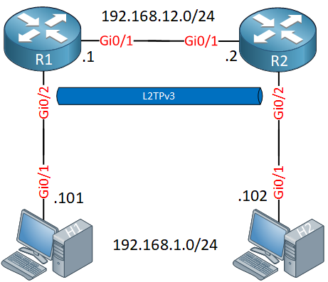
The configuration of L2TPv3 is pretty straightforward. Let’s use the following topology:

We have two routers, R1 and R2. We’ll configure L2TPv3 on these two routers so that H1 and H2 can reach each other.
Our hosts will be in the same L2 domain so let’s configure an IP address on each so that they are on the same subnet:
H1(config)#interface GigabitEthernet 0/1
H1(config-if)#ip address 192.168.1.101 255.255.255.0H2(config)#interface GigabitEthernet 0/1
H2(config-if)#ip address 192.168.1.102 255.255.255.0Let’s configure the link in between R1 and R2:
R1(config)#interface GigabitEthernet 0/1
R1(config-if)#ip address 192.168.12.1 255.255.255.0R2(config)#interface GigabitEthernet 0/1
R2(config-if)#ip address 192.168.12.2 255.255.255.0Now we can focus on the L2TPv3 configuration. First, we create a new pseudowire class. This is the template for the tunnel where we set the source interface and encapsulation type:
R1 & R2
(config)#pseudowire-class R1_R2
(config-pw-class)#encapsulation l2tpv3
(config-pw-class)#ip local interface GigabitEthernet 0/1
Now we need to bind the pseudowire to the interface where we want to bridge our L2 traffic. In our topology, that’s the GigabitEthernet 0/2 interface. This is done with the xconnect command. We also have to set a unique virtual circuit ID (I’ll use 12), set the remote peer IP address, and refer to the pseudowire class we created:
R1(config)#interface GigabitEthernet 0/2
R1(config-if)#xconnect 192.168.12.2 12 pw-class R1_R2R2(config)#interface GigabitEthernet 0/2
R2(config-if)#xconnect 192.168.12.1 12 pw-class R1_R2This completes our configuration. When you configure the xconnect command, you’ll see that it supports some sub-commands:
R1(config-if-xconn)#We don’t have to use this for our simple topology but this is where you can configure a backup pseudowire if you want.
Verification
Let’s see if our L2TPv3 configuration is working or not. Let’s start with a quick ping:
H1#ping 192.168.1.102
Type escape sequence to abort.
Sending 5, 100-byte ICMP Echos to 192.168.1.102, timeout is 2 seconds:
!!!!!
Success rate is 100 percent (5/5), round-trip min/avg/max = 6/7/11 ms
Our ping from H1 to H2 is working so that’s looking good. Let’s take a look at some show commands on our routers.
There are a couple of commands you can try:
- show l2tp
- show l2tun
- show xconnect
Let’s try some:
R1#show l2tp session

L2TP Session Information Total tunnels 1 sessions 1

LocID      RemID      TunID      Username, Intf/      State  Last Chg Uniq ID
                                 Vcid, Circuit
925791518  1078883537 296005772  12, Gi0/2            est    00:00:51 0
This gives a quick overview that shows our virtual circuit ID and the interface that the pseudowire is connected to. If you want more detail, add the “all” parameter to this command:
R1#show l2tp session all

L2TP Session Information Total tunnels 1 sessions 1

Session id 925791518 is up, logical session id 32777, tunnel id 296005772
  Remote session id is 1078883537, remote tunnel id 3566820914
  Remotely initiated session
  Unique ID is 0
Session Layer 2 circuit, type is Ethernet, name is GigabitEthernet0/2
  Session vcid is 12
  Circuit state is UP
    Local circuit state is UP
    Remote circuit state is UP
Call serial number is 255000001
Remote tunnel name is R2
  Internet address is 192.168.12.2
Local tunnel name is R1
  Internet address is 192.168.12.1
IP protocol 115
  Session is L2TP signaled
  Session state is established, time since change 00:05:45
    16 Packets sent, 17 received
    3216 Bytes sent, 3293 received
  Last clearing of counters never
  Counters, ignoring last clear:
    16 Packets sent, 17 received
    3216 Bytes sent, 3293 received
    Receive packets dropped:
      out-of-order:             0
      other:                    0
      total:                    0
    Send packets dropped:
      exceeded session MTU:     0
      other:                    0
      total:                    0
  DF bit off, ToS reflect disabled, ToS value 0, TTL value 255
  Sending UDP checksums are disabled
  Received UDP checksums are verified
  No session cookie information available
  FS cached header information:
    encap size = 24 bytes
    45000014 00000000 ff732223 c0a80c01
    c0a80c02 404e74d1
  Sequencing is off
  Conditional debugging is disabled
  SSM switch id is 4096, SSM segment id is 8204
This gives us some interesting output. We see the L2 type (Ethernet), that the tunnel is up, and the number of packets that are sent/received. You can also see the protocol number here (115).
The show xconnect command is a bit similar to the first command. It is a nice quick way to see if the pseudowire is up though:
R1#show xconnect all
Legend:    XC ST=Xconnect State  S1=Segment1 State  S2=Segment2 State
  UP=Up       DN=Down            AD=Admin Down      IA=Inactive
  SB=Standby  HS=Hot Standby     RV=Recovering      NH=No Hardware

XC ST  Segment 1                         S1 Segment 2                         S2
------+---------------------------------+--+---------------------------------+--
UP pri   ac Gi0/2:4(Ethernet)            UP l2tp 192.168.12.2:12              UP
What does this L2TPv3 encapsulated traffic look like in Wireshark? Here’s an example of the ICMP traffic that I captured:


Hi Rafael,
That is no problem. Here’s a quick example where I run OSPF on hosts in the topology I used to test L2TPv3:
And we get neighbors:
Hope this helps!
Rene
I have an interesting question - what happens if you have multiple VLANs running and you want to trunk all of them instead of just 1 VLAN?
Hi Chris,
This is no problem.
H1:
H2:
And a ping:
Rene
Hello Kyi
Unfortunately L2TPv3 is a point to point technology. However, you can create multiple point to point L2TPv3 connections to achieve a similar result.
I hope this has been helpful!
Laz
Hello Rene
was going to CCIE written blue print..not able to find this 2 topic in l3vpn tunneling section
please can you help or i am missing …
4.1.h (i) MPLS-VPLS general principals
4.1.h (ii) OTV general principals