Lesson Contents
The Raspberry Pi is a great little Linux (Debian) box that has become very popular. It’s cheap (about $25) and since it’s running Linux it can be used for many different applications. I’m using one as a Cisco Console / Terminal server so I don’t have to connect Cisco devices directly to my laptop anymore. The Raspberry Pi has been configured so that I can access a Cisco console port from the wired or wireless network. Here’s what it looks like:
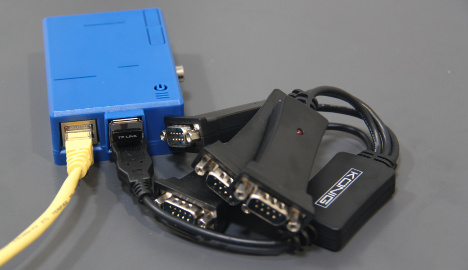
So what does it do?
- The Konig USB to Serial RS-232 cable lets me connect to 4 Cisco devices simultaneously.
- Access to these Cisco devices from the wired network.
- Access to these Cisco devices for wireless users through the little D-Link Wireless USB adapter that is configured as an access point.
In this lesson, I will show you how to configure your Raspberry Pi as a Cisco console server. We’ll start by installing the latest version of Raspbian…
Installing Raspbian
Start by downloading the latest version of Raspbian so that we can install it on an SD card. I will use a Linux computer to extract this image to the SD card of the Raspberry Pi. Insert the SD card in your computer and check which drive letter it has:
# df -lh
Filesystem      Size  Used Avail Use% Mounted on
/dev/sda5       135G  101G   28G  79% /
udev            1.9G  4.0K  1.9G   1% /dev
tmpfs           769M  1.1M  768M   1% /run
none            5.0M     0  5.0M   0% /run/lock
none            1.9G   76K  1.9G   1% /run/shm
/dev/sdc1        30G  6.5G   22G  24% /media/f0dd0487-5e6d-478f-a2ad-db7f9eb3c0c0
/dev/sdb1       125M   97M   29M  78% /media/System
Above, you can see some drives that have been mounted. It’s probably /dev/sdb1 since sda5 and sdc1 are too large. Let’s make sure by looking at fdisk:
# sudo fdisk -l
[sudo] password for renemolenaar:

Disk /dev/sda: 256.1 GB, 256060514304 bytes
255 heads, 63 sectors/track, 31130 cylinders, total 500118192 sectors
Units = sectors of 1 * 512 = 512 bytes
Sector size (logical/physical): 512 bytes / 512 bytes
I/O size (minimum/optimal): 512 bytes / 512 bytes
Disk identifier: 0x0004b282

   Device Boot      Start         End      Blocks   Id  System
/dev/sda1   *        2048      206847      102400    7  HPFS/NTFS/exFAT
/dev/sda2          206848   204802047   102297600    7  HPFS/NTFS/exFAT
/dev/sda3       204804094   500117503   147656705    5  Extended
/dev/sda5       204804096   491962367   143579136   83  Linux
/dev/sda6       491964416   500117503     4076544   82  Linux swap / Solaris

Disk /dev/sdb: 8068 MB, 8068792320 bytes
249 heads, 62 sectors/track, 1020 cylinders, total 15759360 sectors
Units = sectors of 1 * 512 = 512 bytes
Sector size (logical/physical): 512 bytes / 512 bytes
I/O size (minimum/optimal): 512 bytes / 512 bytes
Disk identifier: 0x0003ccba

   Device Boot      Start         End      Blocks   Id  System
/dev/sdb1   *        2048      258047      128000    c  W95 FAT32 (LBA)
/dev/sdb2          258048    15726591     7734272   83  Linux
/dev/sdb is the drive I am looking for. It’s my 8 GB SD card. Let’s unmount /dev/sdb1 so that we can extract Raspbian to this SD card:
# umount /dev/sdb1Now we can extract the image to the SD card:
# dd bs=4M if=2013-05-25-wheezy-raspbian.img of=/dev/sdbThis will take some time, and you won’t see the progress. Grab some coffee, and once it’s done, you can remove the SD card from your computer and insert it into your Raspberry Pi.
Installing ser2net
By default, SSH will be enabled on your Raspberry Pi so you will be able to log in through the network if you don’t have a display connected to it. The default username is ‘pi’, and the password is ‘raspberry’:
# ssh pi@10.56.100.3
pi@10.56.100.3's password:
I don’t like the default hostname of the Pi so I will first give it another name, let’s call it “CONSOLE”. We’ll have to edit the hostname for this:
$ sudo vi /etc/hostnameYou will see the new hostname once you have rebooted your Pi, don’t worry about it for now.
Ser2net lets you access serial ports through TCP, which turns your Pi into a console server. It’s in the repositories but don’t install it using apt-get because it’s not the latest version. We’ll download and compile ser2net ourselves:
$ wget http://downloads.sourceforge.net/project/ser2net/ser2net/ser2net-2.8.tar.gzAnd extract it:
$ tar -xzvf ser2net-2.8.tar.gzAnd install it:
$ cd ser2net-2.8/
$ ./configure
$ make
$ sudo make install
This will take some time since the Raspberry Pi is not a speed champion. Once ser2net is installed, we’ll remove the leftovers:
$ make cleanBefore we configure ser2net we need to know which port your USB to serial cable is using. Use the following command:
$ dmesg | grep tty
[    0.000000] Kernel command line: dma.dmachans=0x7f35 bcm2708_fb.fbwidth=656 bcm2708_fb.fbheight=416 bcm2708.boardrev=0xe bcm2708.serial=0x91681e36 smsc95xx.macaddr=B8:27:EB:68:1E:36 sdhci-bcm2708.emmc_clock_freq=100000000 vc_mem.mem_base=0x1ec00000 vc_mem.mem_size=0x20000000  dwc_otg.lpm_enable=0 console=ttyAMA0,115200 kgdboc=ttyAMA0,115200 console=tty1 root=/dev/mmcblk0p2 rootfstype=ext4 elevator=deadline rootwait
[    0.000000] console [tty1] enabled
[    0.584282] dev:f1: ttyAMA0 at MMIO 0x20201000 (irq = 83) is a PL011 rev3
[    0.908119] console [ttyAMA0] enabled
[  537.324931] usb 1-1.2: FTDI USB Serial Device converter now attached to ttyUSB0
You can see mine is connected to ttyUSB0. Now we can configure ser2net:
$ sudo vi /etc/ser2net.confAnd add the following two lines:
BANNER:banner:NETWORKLESSONS.COM Terminal Server TCP port p device d rn

4001:telnet:0:/dev/ttyUSB0:9600 8DATABITS NONE 1STOPBIT banner
The first line will display a banner to all users who connect, you don’t really need this but it’s a nice extra. The second line is more important, it tells ser2net to listen on TCP port 4001 and to use the /dev/ttyUSB0 device. The baud rate of 9600, 8 data bits, no parity, and 1 stop bit is what Cisco console ports require by default.
Let’s do a quick test to see if we can connect to this port. We’ll have to start ser2net:
$ ser2net -nNow try to telnet to TCP port 4001 from another computer:
# telnet 10.56.100.3 4001
Trying 10.56.100.3...
Connected to 10.56.100.3.
Escape character is '^]'.
Welcome to NETWORKLESSONS.COM Terminal Server TCP port 4001 device /dev/ttyUSB0
We are now connected to the serial port…great! As you can see, it displays the TCP port that we are connected to and the USB device. Let’s make sure that whenever you reboot the Pi that ser2net is started:
$ sudo vi /etc/rc.localAt the bottom of this file, you will find ‘exit 0’. Just above this line, you need to add the following line:
/usr/local/sbin/ser2net -nThe next time you reboot your Pi, it will start ser2net automatically for you. You are now ready to use your new Cisco console server, but I have some extras for you.
Ser2net supports logging and will write all input and output of a session to a file. For me, this is very useful since I can save the output of certain show commands and use them to write lessons later.
Configure ser2net logging
Before we enable logging, you should verify that your Pi has its clock configured correctly. ser2net will add a timestamp to its log files, and logging is pretty much useless if you don’t have the correct date or time.
By default, it will synchronize its time using NTP, but the timezone might be incorrect. Changing the timezone is easy to do:
$ sudo cp /usr/share/zoneinfo/Europe/Amsterdam /etc/localtimeThis will change my timezone to CEST (Central European Time). Let’s verify it:
$ date
Fri Jul 19 11:55:27 CEST 2013
That’s looking good to me. Now we’ll create a folder that will hold our log files. I will save everything in the /var/log/ser2net folder:
$ sudo mkdir /var/log/ser2netNow you need to edit the /etc/ser2net.conf file again and add the following:
TRACEFILE:tr1:/var/log/ser2net/tr-p-Y-M-D-H:i:s.U
4001:telnet:0:/dev/ttyUSB0:9600 8DATABITS NONE 1STOPBIT banner tr=tr1 timestamp
The ‘TRACEFILE’ line is new, and at the end of the 4001:telnet… line, we will add “tr=tr1 timestamp”. This will enable logging for this port and add timestamps to the log files.
You will have to restart ser2net before logging is active. The next time you connect, you will see the log files in the /var/log/ser2net folder:
$ ls /var/log/ser2net
tr-4001-2013-Jul-19-09:18:26.893894
You now have a console server that saves logging information. In the next part, I’ll show you how to enable wireless support and how to secure your Pi:
Wireless Access Point
Most wireless adapters also support access point mode. This is very useful since we can make our Pi broadcast an SSID and let wireless clients connect. This turns our Pi into a wireless console server…nice!
Plug in your wireless USB adapter and see if it’s recognized:
$ lsusb
Bus 001 Device 002: ID 0424:9514 Standard Microsystems Corp.
Bus 001 Device 001: ID 1d6b:0002 Linux Foundation 2.0 root hub
Bus 001 Device 003: ID 0424:ec00 Standard Microsystems Corp.
Bus 001 Device 004: ID 0bda:8179 Realtek Semiconductor Corp.
Bus 001 Device 005: ID 0403:6001 Future Technology Devices International, Ltd FT232 USB-Serial (UART) IC
Remember that the Raspberry Pi’s USB port has limited power, and not all wireless adapters are supported. Look at the elinux Rpi page to see which adapters are supported.
If your USB device is recognized, we still have to check if our wireless drivers are operational:
$ iwconfig
wlan0 unassociated Nickname:"<WIFI@REALTEK>"
Mode:Managed Frequency=2.412 GHz Access Point: Not-Associated
Sensitivity:0/0
Retry:off RTS thr:off Fragment thr:off
Power Management:off
Link Quality:0 Signal level:0 Noise level:0
Rx invalid nwid:0 Rx invalid crypt:0 Rx invalid frag:0
Tx excessive retries:0 Invalid misc:0 Missed beacon:0
If iwconfig doesn’t give you any information, you probably have an issue with drivers.
Once your wireless card is up and running, we will install hostapd. This configures the wireless adapter as an access point:
$ sudo apt-get install hostapdWe’ll configure the wireless adapter to use a static IP address instead of DHCP:
$ sudo vi /etc/network/interfacesRemove the following two lines from this file:
iface wlan0 inet manual

wpa-roam /etc/wpa_supplicant/wpa_supplicant.conf
And replace them with the following lines:
iface wlan0 inet static
address 172.16.82.254
netmask 255.255.255.0
Our wlan0 interface will use static IP address 172.16.82.254 /24. Now we’ll configure hostapd to set some parameters for the access point:
$ sudo vi /etc/hostapd/hostapd.confssid=Console
wpa_passphrase=mysecurepassphrase
wpa=3You can leave most of the settings in this file alone, but I will change the SSID and the WPA passphrase. The passphrase will be “mysecurepassphrase” and wpa=3 means we will support WPA and WPA2. Let’s start hostapd:
$ sudo service hostapd startTo make sure hostapd runs after rebooting the Pi, we’ll add it to the startup list:
$ sudo update-rc.d hostapd enableYour Raspberry Pi should now be broadcasting SSID “Console” but wireless clients must configure a static IP address. We’ll fix this by installing a DHCP server:
$ sudo apt-get install dnsmasqAt the bottom of this file, you should add the following two lines:
interface=wlan0
dhcp-range=172.16.82.10,172.16.82.100,12h
This ensures that the DHCP server only runs for wireless clients and that we’ll use 172.16.82.10 – 172.16.82.100 for DHCP clients.
Restart the DHCP server:
$ sudo service dnsmasq restart
[ ok ] Restarting DNS forwarder and DHCP server: dnsmasq.
And make sure it boots at startup:
$ sudo update-rc.d dnsmasq enableYour Raspberry Pi is now configured as an access point. Wireless clients can now connect to it and access the console port by telnetting to 172.16.82.254:4001.
In the final part of this lesson, we’ll take a look at some security measures. Your Pi is using a default username/password, and the firewall is allowing all traffic.
Security
Even though the Pi is a little box, it’s still a fully functional Linux server. It’s best to take some security measures to protect it. I will change the default username, tighten SSH security a bit and add some rules to the IPTables firewall.
Change username
First, I’ll replace the default user ‘pi’ with my own username:
$ sudo adduser renemolenaar
Adding user `renemolenaar' ...
Adding new group `renemolenaar' (1002) ...
Adding new user `renemolenaar' (1001) with group `renemolenaar' ...
Creating home directory `/home/renemolenaar' ...
Copying files from `/etc/skel' ...
Don’t forget to add a password:
$ sudo passwd renemolenaar
Enter new UNIX password:
Retype new UNIX password:
passwd: password updated successfully
And we need to add the new user to the sudoers list, or you can’t run any important commands:
$ sudo vi /etc/sudoersChange the following line:
pi ALL=(ALL) NOPASSWD: ALLto:
renemolenaar ALL=(ALL) NOPASSWD: ALLNow try if you are able to log into the Pi using your new username and if you can use sudo. When it’s working, we’ll delete the old ‘pi’ account:
$ sudo deluser pi
Removing user `pi' ...
Warning: group `pi' has no more members.
Done.
I always like to change the default SSH port and ensure that the root user can’t log in through SSH directly:
$ sudo vi /etc/ssh/sshd_configNow change the following line:
PermitRootLogin yesTo:
PermitRootLogin noAnd change the port number to something else:
Port 22To:
Port 10050Don’t forget to restart SSH to apply the changes you made:
$ sudo service ssh restartThis makes SSH a little bit more secure.
IPTables Firewall
Your Raspberry Pi has the IPtables firewall installed on it by default, but we’ll have to add some rules ourselves. I want to make sure outside LAN users can only connect to TCP 4001 for the console port and TCP port 10050 to access SSH. The same rules will apply to wireless users except that they will also request an IP address through DHCP.
Create a new file for IPTables:
$ sudo vi /etc/iptables-rulesAnd add the following lines to it:
*filter
:INPUT ACCEPT [0:0]
:FORWARD ACCEPT [0:0]
:OUTPUT ACCEPT [0:0]
-A INPUT -i lo -j ACCEPT
-A INPUT -m conntrack --ctstate RELATED,ESTABLISHED -j ACCEPT
# LAN Rules
-A INPUT -i eth0 -p tcp -m tcp --dport 4001 -j ACCEPT
-A INPUT -i eth0 -p tcp -m tcp --dport 10050 -j ACCEPT
# WIRELESS Rules
-A INPUT -i wlan0 -p udp -m udp --dport 67 -j ACCEPT
-A INPUT -i wlan0 -p tcp -m tcp --dport 4001 -j ACCEPT
-A INPUT -i wlan0 -p tcp -m tcp --dport 10050 -j ACCEPT # Allow ICMP packets necessary for MTU path discovery -A INPUT -p icmp --icmp-type fragmentation-needed -j ACCEPT # Allow echo request -A INPUT -p icmp --icmp-type 8 -j ACCEPT -A INPUT -j DROP COMMIT
Save your file and load the firewall rules:
$ sudo iptables-restore < /etc/iptables-rulesLet’s make sure these rules are loaded when the Pi reboots:
$ sudo vi /etc/network/interfacesAdd the following line at the bottom of the interfaces file:
pre-up /sbin/iptables-restore < /etc/iptables-rulesThis is a good moment to reboot your Pi and verify that iptables is running:
$ sudo iptables -L
Chain INPUT (policy ACCEPT)
target     prot opt source               destination
ACCEPT     all  --  anywhere             anywhere
ACCEPT     all  --  anywhere             anywhere             ctstate RELATED,ESTABLISHED
ACCEPT     tcp  --  anywhere             anywhere             tcp dpt:4001
ACCEPT     tcp  --  anywhere             anywhere             tcp dpt:10050
ACCEPT     tcp  --  anywhere             anywhere             tcp dpt:4001
ACCEPT     tcp  --  anywhere             anywhere             tcp dpt:10050
ACCEPT     udp  --  anywhere             anywhere             udp dpt:bootps
ACCEPT     icmp --  anywhere             anywhere             icmp fragmentation-needed
ACCEPT     icmp --  anywhere             anywhere             icmp echo-request
DROP       all  --  anywhere             anywhere

Chain FORWARD (policy ACCEPT)
target     prot opt source               destination

Chain OUTPUT (policy ACCEPT)
target     prot opt source               destination
Your Raspberry Pi is now protected by IPTables.
I hope this lesson has been useful to you in transforming your Little Pi into an awesome wired/wireless Console server. If you enjoy this setup as much as I do, let me know by leaving a comment!
Where did you purchase your Konig usb to serial adapter?
Hi Rowell,
I purchased it from some Dutch webshop a couple of years ago, it seems Konig doesn’t sell them anymore (too bad). Best to google for “4 Port USB RS-232” , I’m sure some other vendors still sell them…
Rene
Got things working. Thanks! Great tutorial.
Thanks for this great write-up; I just put together a very similar setup. I used a StarTech 4-port serial “hub” I bought off Amazon (http://www.amazon.com/dp/B000YB0NQG/), since the one mentioned in this write-up I could not find in the U.S.; it appears to use the same FTDI chip-set.
One caveat I did run into is UDEV re-assigning what ports were mapped to /dev/ttyUSB*. I found this out the hard way trying to remotely configure a router and the port no longer worked. Turns out it moved. I found the article below to add UDEV rules to manually map a device sy
... Continue reading in our forumFor US readers:
You may buy the quad serial to USB from Amazon, using this link:
In case the link changes, here is the name of the item:
GearMo® 36inch Quad Port FTDI USB to Serial Cable for MA PC Linux with Windows Certified Drivers
Model # USA-FTDI4X
As of this post, it costs $48.29.