Lesson Contents
Asymmetric routing is not uncommon and it doesn’t always cause issues. There are however a number of scenarios where it could cause problems. For example:
- Traffic that is translated by a NAT router should also use the same router for return traffic. Otherwise there’s no way to translate the packets back to their original IP address.
- Firewalls keep track of the state of connections. Traffic should leave your network through the firewall so that return traffic is able to get back in. Otherwise it will be dropped.
- Unicast flooding can occur when a switch is unable to learn the outgoing interface for a destination MAC address.
In this lesson we’ll discuss the third problem, a switch that doesn’t know a destination MAC address and that will keep flooding the network with unknown unicast traffic.
Topology
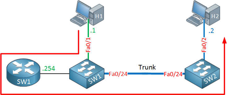
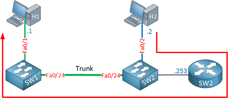
To demonstrate this problem I will use the following topology:
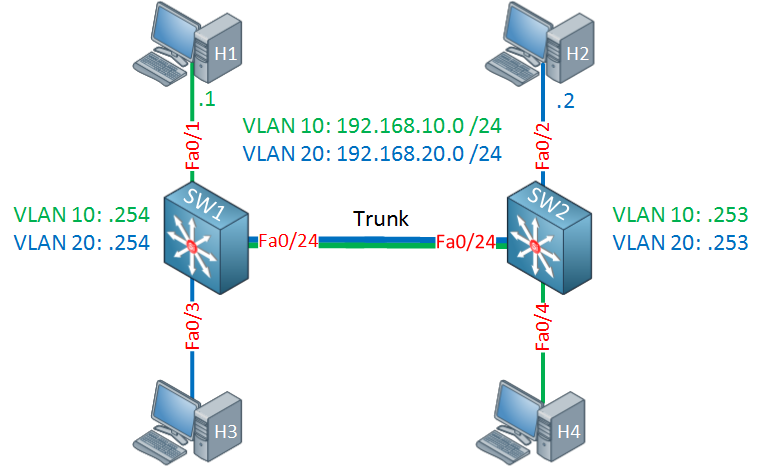
Let me explain the topology above:
- There are two multilayer switches, SW1 and SW2. Between these switches we have a trunk for VLAN 10 and 20.
- SW1 and SW2 have SVI interfaces with an IP address for VLAN 10 and 20.
- Host 1 and 4 are in VLAN 10.
- Host 2 and 3 are in VLAN 20.
- Host 1 uses 192.168.10.254 (SW1) as its default gateway.
- Host 2 uses 192.168.20.253 (SW2) as its default gateway.
Let me show you the interface configuration and routing tables of both switches:
SW1#
interface FastEthernet0/1
 switchport access vlan 10
 switchport mode access

interface FastEthernet0/3
 switchport access vlan 20
 switchport mode access

interface FastEthernet0/24
 switchport trunk encapsulation dot1q
 switchport mode trunk

interface Vlan10
 ip address 192.168.10.254 255.255.255.0

interface Vlan20
 ip address 192.168.20.254 255.255.255.0
Here’s the routing table of SW1:
SW1#show ip route connected
C    192.168.10.0/24 is directly connected, Vlan10
C    192.168.20.0/24 is directly connected, Vlan20
And here’s SW2:
SW2#
interface FastEthernet0/2
 switchport access vlan 20
 switchport mode access

interface FastEthernet0/4
 switchport access vlan 10
 switchport mode access

interface FastEthernet0/24
 switchport trunk encapsulation dot1q
 switchport mode trunk

interface Vlan10
 ip address 192.168.10.253 255.255.255.0

interface Vlan20
 ip address 192.168.20.253 255.255.255.0
And the routing table of SW2:
SW2#show ip route connected
C    192.168.10.0/24 is directly connected, Vlan10
C    192.168.20.0/24 is directly connected, Vlan20
The configuration is pretty straight forward, the hosts are in different VLANs and each switch has a SVI for each VLAN. This design however has some major issues…
Traffic path from host 1 to host 2
To show you what is wrong with this topology we will send some packets from host 1 to host 2 and we will take a close look at the traffic path. Let’s send a ping from host 1 to host 2:
H1#ping 192.168.20.2
Type escape sequence to abort.
Sending 5, 100-byte ICMP Echos to 192.168.20.2, timeout is 2 seconds:
!!!!!
Success rate is 100 percent (5/5), round-trip min/avg/max = 1/3/8 ms
Our pings are succesful. When host 1 sends the IP packet it will end up at its default gateway which is SW1.
SW1 is a multilayer switch so it has two roles…routing and switching. Once it receives the IP packet in VLAN 10 it will check its routing table to see if it knows where to forward this packet to:
SW1#show ip route connected
C    192.168.10.0/24 is directly connected, Vlan10
C    192.168.20.0/24 is directly connected, Vlan20
SW1 has a VLAN 20 interface so the destination is directly connected to it. To better understand how a multilayer switch works, take a look at this picture:
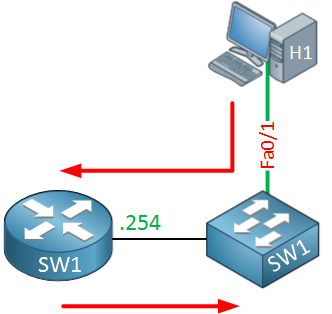
Above you can see that SW1 receives a packet from host 1 on its switchport in VLAN 10. This is then forwarded to the “router” part which checks the routing table and decides that the destination is in VLAN 20 which is directly connected. SW1 will now do an ARP request to find the MAC address of host 2:
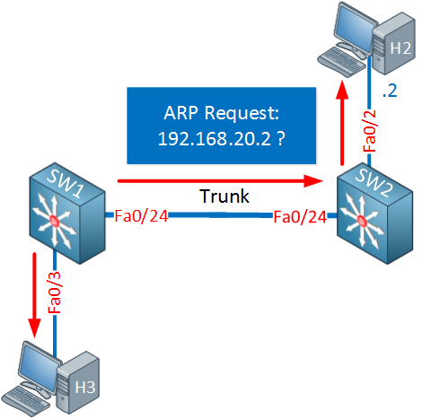
This ARP request will be flooded in VLAN 20 and eventually ends up at host 2 which will reply with an ARP reply:
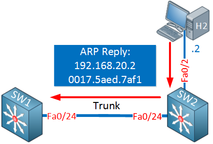
SW1 will store this entry in its ARP table:
SW1#show ip arp 192.168.20.2
Protocol  Address          Age (min)  Hardware Addr   Type   Interface
Internet  192.168.20.2           227  0017.5aed.7af1  ARPA   Vlan20
Since the ARP reply is a unicast message, SW1 will also learn the source MAC address of host 2. It’s also possible that it learned this MAC address when host 2 did an ARP request for its default gateway. We can find it in the MAC address table:
SW1#show mac address-table address 0017.5aed.7af1
          Mac Address Table
-------------------------------------------

Vlan    Mac Address       Type        Ports
----    -----------       --------    -----
  20    0017.5aed.7af1    DYNAMIC     Fa0/24
Total Mac Addresses for this criterion: 1
The frame that carries the IP packet from host 1 to host 2 is now switched by SW1 to SW2 which also has an entry in its MAC address table:
SW2#show mac address-table address 0017.5aed.7af1
          Mac Address Table
-------------------------------------------

Vlan    Mac Address       Type        Ports
----    -----------       --------    -----
  20    0017.5aed.7af1    DYNAMIC     Fa0/2
Total Mac Addresses for this criterion: 1
The packet from host 1 made it to its destination, host 2. Here’s a visualization of this process:
The packet from host 1 is sent to its default gateway (SW1) which checks its routing table, decides that VLAN 20 is directly connected and forwards the frame towards SW2. SW2 wil deliver it to host 2. So far so good, let’s check what the return traffic looks like now.
Traffic path from host 2 to host 1
When host 2 receives the IP packet from host 1 it will reply to it. It will create an IP packet with source address 192.168.20.2 and destination 192.168.10.1. Since the destination is outside of its own subnet, it will send it to the default gateway (SW2).
SW2 will check its routing table and determines that VLAN 10 is directly connected so it will try to deliver it directly to host 1:
SW2#show ip route connected
C    192.168.10.0/24 is directly connected, Vlan10
C    192.168.20.0/24 is directly connected, Vlan20
Here’s a visualization of this process:
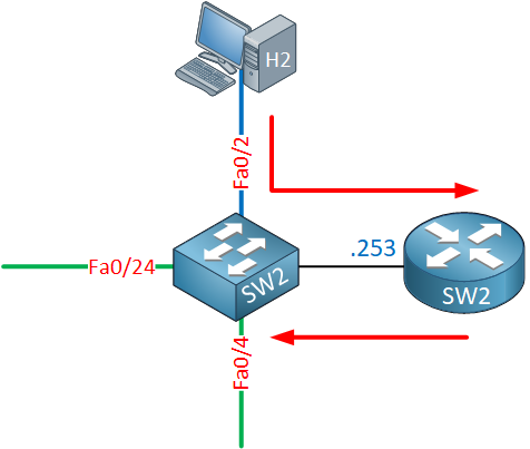
To deliver the frame that carries the IP packet from host 2 to host 1, SW2 has to know the MAC address of host 1. It will send an ARP request which is flooded within VLAN 10:
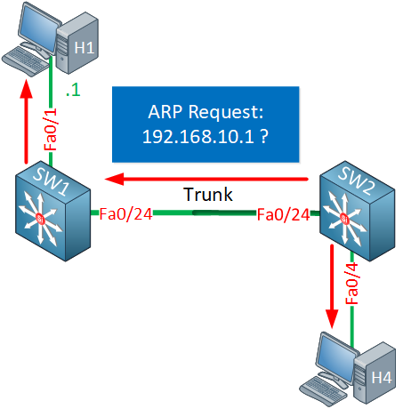
Host 1 will receive it and will answer with an ARP reply:
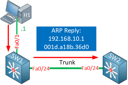
Great, SW2 now has an entry in the ARP table for host 1:
SW2#show ip arp 192.168.10.1
Protocol  Address          Age (min)  Hardware Addr   Type   Interface
Internet  192.168.10.1           224  001d.a18b.36d0  ARPA   Vlan10
Since the ARP reply is a unicast message, SW2 also learned the MAC address of host 1 if it didn’t learn it before from the ARP request of host 1 for its default gateway:
SW2#show mac address-table address 001d.a18b.36d0
          Mac Address Table
-------------------------------------------

Vlan    Mac Address       Type        Ports
----    -----------       --------    -----
  10    001d.a18b.36d0    DYNAMIC     Fa0/24
Total Mac Addresses for this criterion: 1
SW2 will now switch the frame to SW1 which will forward it to host 1:
SW1#show mac address-table address 001d.a18b.36d0
          Mac Address Table
-------------------------------------------

Vlan    Mac Address       Type        Ports
----    -----------       --------    -----
  10    001d.a18b.36d0    DYNAMIC     Fa0/1
Total Mac Addresses for this criterion: 1
And our IP packet makes it back to host 1. Here’s a visualization of the traffic path from host 2 to host 1:
The IP packet from host 2 is routed by SW2 which then switches it to SW1 and eventually it ends up at host 1. Let’s compare the traffic path from host 1 to host 2 and vice versa:
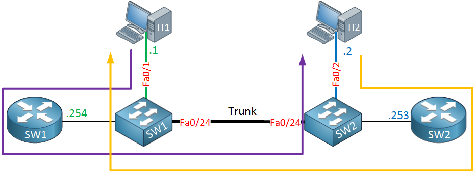
The purple line is the traffic from host 1 to host 2, the orange line is for the return traffic from host 2 to host 1. This is asymmetric traffic at its finest.
So far life is good, our hosts are able to communicate with each other and there are no issues. Now let me show you where things will get funky…

Rene,
Great lesson, however I have a questions if you please clarify.
How do I change the ARP table timeout so it matches the aging time of the MAC address table.?
How can we make one vlan as gateway if we have multiple vlans on the distribution switch connects to different closets on the floors? For example we have
vlan 2 - serves second floor and it is on our distribution
inter vlan2
ip address 192.168.2.1/24
vlan3- serves 3rd floor
inter vlan 3
ip address 192.168.3.1/24
In the closet 2 floor access layer switch has an ip address of 192.168.2.5 with default
... Continue reading in our forumHi Hamood,
You can use the “ip arp timeout” command on the switch to change it.
For each VLAN you will need a gateway but you will have to consider which device(s) you use as the gateway. Like in my example, by using two different switches like this we got this issue. If I would use one switch as the gateway for both VLANs then I wouldn’t have this problem.
Rene
Great lesson rene, is it really advisable to have the ARP Timeout = Aging time of Mac address?
Hi John,
Thanks. It depends on your design, if it is similar to my example then yes that would be a good idea.
Rene
thanks. what if i only have 1 multilayer switch? then it is not needed to have the ARP timeout equals to the aging of mac? if its true then, is there a disadvantage if i make the ARP timeout = to aging of mac with a 1 multilayer switch only?
thank you!