Lesson Contents
This lesson explains how to use OSPF as the PE-CE routing protocol for MPLS L3 VPN. The configuration is very similar to PE-CE RIP or PE-CE EIGRP but OSPF has some extra options as a link-state routing protocol.
The first part is about configuring LDP, VRFs and iBGP between the PE routers. This is the same as my previous lessons so you might want to skip to the PE-CE OSPF section.
Here’s the topology we will use:
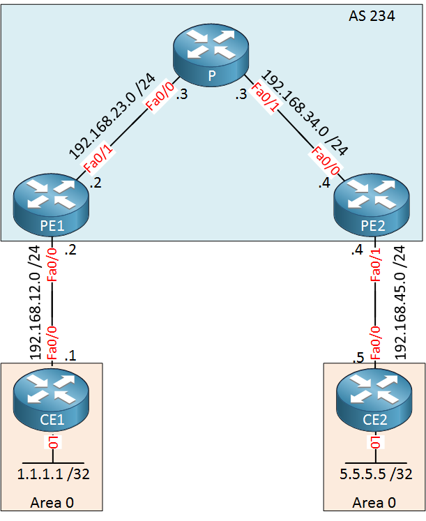
Above we have 5 routers. CE and CE2 belong to the customer who wants to run OSPF between their sites. The service provider has two PE routers and one P router in the middle.
Configuration
IGP and LDP
Let’s prepare the service provider routers. We need an IGP (OSPF) and LDP on the PE1, PE2 and P router.
PE1(config)#interface loopback 0
PE1(config-if)#ip address 2.2.2.2 255.255.255.255P(config)#interface loopback 0
P(config-if)#ip address 3.3.3.3 255.255.255.255PE2(config)#interface loopback 0
PE2(config-if)#ip address 4.4.4.4 255.255.255.255Now we can configure OSPF for routing in the service provider network:
PE1(config)#router ospf 1
PE1(config-router)#network 192.168.23.0 0.0.0.255 area 0
PE1(config-router)#network 2.2.2.2 0.0.0.0 area 0
PE1(config-router)#mpls ldp autoconfigP(config)#router ospf 1
P(config-router)#network 192.168.23.0 0.0.0.255 area 0
P(config-router)#network 192.168.34.0 0.0.0.255 area 0
P(config-router)#network 3.3.3.3 0.0.0.0 area 0
P(config-router)#mpls ldp autoconfigPE2(config)#router ospf 1
PE2(config-router)#network 192.168.34.0 0.0.0.255 area 0
PE2(config-router)#network 4.4.4.4 0.0.0.0 area 0
PE2(config-router)#mpls ldp autoconfigThis takes care of IGP and LDP. Make sure you have LDP neighbors before we continue:
P#show mpls ldp neighbor | include Peer
    Peer LDP Ident: 2.2.2.2:0; Local LDP Ident 3.3.3.3:0
    Peer LDP Ident: 4.4.4.4:0; Local LDP Ident 3.3.3.3:0
Our P router in the middle has two neighbors so this is looking good. Just in case, let’s verify if there is connectivity between PE1 and PE2:
PE1#traceroute 4.4.4.4 source loopback 0
Type escape sequence to abort.
Tracing the route to 4.4.4.4
VRF info: (vrf in name/id, vrf out name/id)
  1 192.168.23.3 [MPLS: Label 17 Exp 0] 0 msec 0 msec 4 msec
  2 192.168.34.4 0 msec 0 msec *
The PE routers are able to reach each others loopback interfaces and we are using label switching.
VRFs on the PE Routers
Our next step in the configuration is to configure the VRFs. I will use a VRF called “CUSTOMER”, the route distinguisher and route-target will be 1:1.
PE1 & PE2
(config)#ip vrf CUSTOMER
(config-vrf)#rd 1:1
(config-vrf)#route-target both 1:1
Don’t forget to add the interfaces facing the customer routers into the VRF:
PE1(config)#interface FastEthernet 0/0
PE1(config-if)#ip vrf forwarding CUSTOMER
PE1(config-if)#ip address 192.168.12.2 255.255.255.0PE2(config)#interface FastEthernet 0/1
PE2(config-if)#ip vrf forwarding CUSTOMER
PE2(config-if)#ip address 192.168.45.4 255.255.255.0Let’s check if the PE routers are able to ping the CE routers from the VRF:
PE1#ping vrf CUSTOMER 192.168.12.1
Type escape sequence to abort.
Sending 5, 100-byte ICMP Echos to 192.168.12.1, timeout is 2 seconds:
!!!!!
Success rate is 100 percent (5/5), round-trip min/avg/max = 1/2/4 msPE2#ping vrf CUSTOMER 192.168.45.5
Type escape sequence to abort.
Sending 5, 100-byte ICMP Echos to 192.168.45.5, timeout is 2 seconds:
!!!!!
Success rate is 100 percent (5/5), round-trip min/avg/max = 1/2/4 msSo far so good…
IBGP between PE1 and PE2
Our two PE routers require iBGP to exchange the VPNv4 routes. Let’s configure this:
PE1(config)#router bgp 234
PE1(config-router)#neighbor 4.4.4.4 remote-as 234
PE1(config-router)#neighbor 4.4.4.4 update-source loopback 0
PE1(config-router)#address-family vpnv4
PE1(config-router-af)#neighbor 4.4.4.4 activatePE2(config)#router bgp 234
PE2(config-router)#neighbor 2.2.2.2 remote-as 234
PE2(config-router)#neighbor 2.2.2.2 update-source loopback 0
PE2(config-router)#address-family vpnv4
PE2(config-router-af)#neighbor 2.2.2.2 activate Before we continue we should check if our routers have formed an IBGP neighbor adjacency:
PE1#show bgp vpnv4 unicast all summary
BGP router identifier 2.2.2.2, local AS number 234
BGP table version is 1, main routing table version 1

Neighbor        V           AS MsgRcvd MsgSent   TblVer  InQ OutQ Up/Down  State/PfxRcd
4.4.4.4         4          234       5       6        1    0    0 00:01:03        0
Great, the BGP session has been established.
OSPF between PE and CE Routers
Now we can work on OSPF between the PE and CE routers. Let’s start with CE1 and CE2 first:
CE1(config)#interface loopback 0
CE1(config-if)#ip address 1.1.1.1 255.255.255.255

CE1(config)#router ospf 1
CE1(config-router)#network 192.168.12.0 0.0.0.255 area 0
CE1(config-router)#network 1.1.1.1 0.0.0.0 area 0CE2(config)#interface loopback 0
CE2(config-if)#ip address 5.5.5.5 255.255.255.255
CE2(config)#router ospf 1
CE2(config-router)#network 192.168.45.0 0.0.0.255 area 0
CE2(config-router)#network 5.5.5.5 0.0.0.0 area 0Each CE router has a loopback which is advertised in OSPF. Now we can configure OSPF on the PE routers for the customer VRF:
PE1(config)#router ospf 2 vrf CUSTOMER
PE1(config-router)#network 192.168.12.0 0.0.0.255 area 0PE2(config)#router ospf 2 vrf CUSTOMER
PE2(config-router)#network 192.168.45.0 0.0.0.255 area 0Unlike RIP or EIGRP, we don’t use an address-family but a different process for a VRF. Let’s see if we have learned anything:
PE1#show ip route vrf CUSTOMER ospf

      1.0.0.0/32 is subnetted, 1 subnets
O 1.1.1.1 [110/2] via 192.168.12.1, 16:01:37, FastEthernet0/0PE2#show ip route vrf CUSTOMER ospf
5.0.0.0/32 is subnetted, 1 subnets
O 5.5.5.5 [110/2] via 192.168.45.5, 00:01:39, FastEthernet0/1Great, our PE routers learned the loopback interfaces from the CE routers. Let’s redistribute this into BGP:
PE1 & PE2
(config)#router bgp 234
(config-router)#address-family ipv4 vrf CUSTOMER
(config-router-af)#redistribute ospf 2
If everything went ok, we should now have some VPNv4 routes:
PE1#show bgp vpnv4 unicast vrf CUSTOMER
BGP table version is 7, local router ID is 3.3.3.3
Status codes: s suppressed, d damped, h history, * valid, > best, i - internal,
              r RIB-failure, S Stale, m multipath, b backup-path, x best-external, f RT-Filter
Origin codes: i - IGP, e - EGP, ? - incomplete

   Network          Next Hop            Metric LocPrf Weight Path
Route Distinguisher: 1:1 (default for vrf CUSTOMER)
*> 1.1.1.1/32       192.168.12.1             2         32768 ?
*>i5.5.5.5/32       4.4.4.4                  2    100      0 ?
*> 192.168.12.0     0.0.0.0                  0         32768 ?
*>i192.168.45.0 4.4.4.4 0 100 0 ?PE2#show bgp vpnv4 unicast vrf CUSTOMER
BGP table version is 7, local router ID is 192.168.34.4
Status codes: s suppressed, d damped, h history, * valid, > best, i - internal,
r RIB-failure, S Stale, m multipath, b backup-path, x best-external, f RT-Filter
Origin codes: i - IGP, e - EGP, ? - incomplete
Network Next Hop Metric LocPrf Weight Path
Route Distinguisher: 1:1 (default for vrf CUSTOMER)
*>i1.1.1.1/32 2.2.2.2 2 100 0 ?
*> 5.5.5.5/32 192.168.45.5 2 32768 ?
*>i192.168.12.0 2.2.2.2 0 100 0 ?
*> 192.168.45.0 0.0.0.0 0 32768 ?Exellent, we have VPNv4 routes. You can also see that the metric from OSPF (cost 2) has been saved in the BGP MED attribute. Now let’s redistribute these VPNv4 routes back into OSPF:
PE1 & PE2
(config)#router ospf 2 vrf CUSTOMER
(config-router)#redistribute bgp 234 subnets
Our configuration is now complete.
Verification
First we’ll check if we have connectivity between our CE routers. Did they learn anything?
CE1#show ip route ospf

      5.0.0.0/32 is subnetted, 1 subnets
O IA     5.5.5.5 [110/3] via 192.168.12.2, 00:02:19, FastEthernet0/0
O IA 192.168.45.0/24 [110/2] via 192.168.12.2, 00:02:19, FastEthernet0/0CE2#show ip route ospf
1.0.0.0/32 is subnetted, 1 subnets
O IA 1.1.1.1 [110/3] via 192.168.45.4, 00:02:43, FastEthernet0/0
O IA 192.168.12.0/24 [110/2] via 192.168.45.4, 00:02:43, FastEthernet0/0Our CE routers have learned each others networks. There’s something interesting in the output above…normally when we redistribute something into OSPF then our prefixes show up as O E2 or E1, now we seem to have O IA prefixes. I’ll explain why in a bit, first let’s see if we have connectivity:
CE1#ping 5.5.5.5 source loopback 0
Type escape sequence to abort.
Sending 5, 100-byte ICMP Echos to 5.5.5.5, timeout is 2 seconds:
Packet sent with a source address of 1.1.1.1
!!!!!
Success rate is 100 percent (5/5), round-trip min/avg/max = 1/2/4 ms
Our two CE routers are able to reach each other, let’s try a trace as well:
CE1#traceroute 5.5.5.5 source loopback 0
Type escape sequence to abort.
Tracing the route to 5.5.5.5
VRF info: (vrf in name/id, vrf out name/id)
  1 192.168.12.2 0 msec 0 msec 4 msec
  2 192.168.23.3 [MPLS: Labels 17/16 Exp 0] 0 msec 0 msec 4 msec
  3 192.168.45.4 [MPLS: Label 16 Exp 0] 0 msec 0 msec 4 msec
  4 192.168.45.5 0 msec 0 msec *
Everything seems to be working, the CE routers are able to reach each other and above you can see the transport label (17) and VPN label (16).
There’s a couple of things left I’d like to explain however, let’s think about the prefixes that we have seen on the CE routers.
Our CE routers advertise routes to the PE routers who redistribute it into BGP so they become VPNv4 routes. These VPNv4 routes are exchanged from one PE router to another. Once a PE router receives a VPNv4 route and redistributes it into OSPF, how does it know what LSA type to use and to what area the prefix belongs? Also, how is it possible that redistributed routes show up as inter-area routes?
OSPF works a bit different when we use it as the PE-CE routing protocol, I’ll give you the short version here but if you want to know all details you can check RFC 4577.
Both of our customer sites are using OSPF area 0, normally it’s impossible to have two backbone areas unless you connect them to each other with a virtual link. When we use MPLS L3 VPN, the service provider network is seen by OSPF as the superbackbone:

Hi Rene,
I always wonder how different LOCATIONS but same customer will use the same area 0 but you just clarify this.
Well explain and I am having a lot of fun. I will be preparing for the CCIE written and just started with MPLS Fundamentals book.
Is there a test for the MPLS class?
Thanks
Hi Rene,
I have seen some CE routers configure with this other statements and I was under the impression that we are just suppose to configure EBGP and redistribute OSPF but this CE has attributes that we configure on our example on the PE. Why? Are these extra statements on the CE that have no effect?. I removed the public ip address and the AS#.
... Continue reading in our forumHi Alfredo,
This config is from a CE router? It seems like the customer is running OSPF on their network but they use BGP to advertise their prefixes to the PE router (if 1.1.1.1 is the PE router). That’s not uncommon.
There used to be a MPLS exam in the CCIP track but it’s gone now.
Rene
Hi Rene,
I love the Configuration tabs at the bottom of the page. This and the videos really make your website interactive and fun. Would be great if they were found in each of your topics. But I know your website is always being updated for the best.
Thanks,
Mario
Hi Mario,
Thanks! I thought it would be a good idea to add these, makes it easy to try something yourself if you want.
From now on I’m also adding the capture files so anyone can see them, here’s an example:
https://www.cloudshark.org/captures/7441e9fb421e
Rene