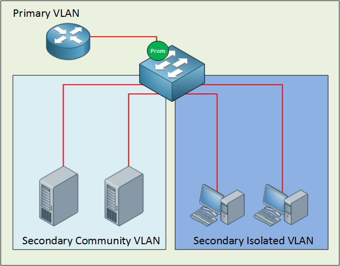
In a previous lesson, I explained the protected port feature on Cisco Catalyst Switches. This time we will look at the private VLAN which I can best describe as protected ports on steroids. If you have no idea what a protected port or VLAN is, I highly recommend reading my previous lesson first. Having said that, let’s get started with a nice topology picture:
Many network students believe private VLANs are very complex when they see this for the first time. I’m going to break it down and explain to you how it works.
The private VLAN always has one primary VLAN. Within the primary VLAN, you will find the promiscuous port. In my picture above, you can see a router connected to a promiscuous port. All other ports can communicate with the promiscuous port. Within the primary VLAN, you will encounter one or more secondary VLANs. There are two types:
- Community VLAN: All ports within the community VLAN can communicate with each other and the promiscuous port.
- Isolated VLAN: All ports within the isolated VLAN are unable to communicate with each other, but they can communicate with the promiscuous port.

The names for these secondary VLANs are well-chosen if you ask me. In a community, everyone can talk to each other. When you are isolated, you can only talk to yourself or, in the case of our private VLANs…the promiscuous port.
Secondary VLANs can always communicate with the promiscuous port but never with other secondary VLANs! Are you following me so far? If so…good! If you are still a little fuzzy, don’t worry. I’m going to show you the configuration and demonstrate to you how this works.
Configuration
First, let me show you the topology that I will use for this demonstration:
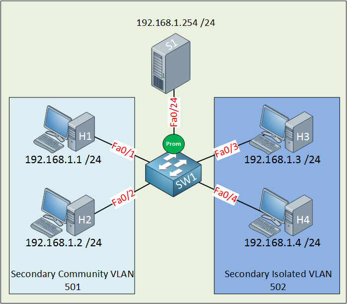
Let me sum up what we have here:
- The primary VLAN has the number 500.
- The secondary community VLAN has the number 501.
- The secondary isolated VLAN has the number 502.
- I just made up these VLAN numbers; you can use whatever you like.
- H1 and H2 in the community VLAN should be able to reach each other and also the server connected to the promiscuous port.
- H3 and H4 in the isolated VLAN can only communicate with the server on the promiscuous port.
- The server should be able to reach all ports.
Let’s get started!
SW1(config)#vtp mode transparent
Setting device to VTP TRANSPARENT mode.
Configuring private VLANs requires us to change the VTP mode to Transparent.
SW1(config)#vlan 501
SW1(config-vlan)#private-vlan community
SW1(config-vlan)#vlan 500
SW1(config-vlan)#private-vlan primary
SW1(config-vlan)#private-vlan association add 501
Let’s start with the configuration of the community VLAN. First, I create VLAN 501 and tell the switch that this is a community VLAN by typing the private-vlan community command. Secondly, I am creating VLAN 500 and configuring it as the primary VLAN with the private-vlan primary command. Last but not least, I need to tell the switch that VLAN 501 is a secondary VLAN by using the private-vlan association command.
SW1(config)#interface range fa0/1 - 2
SW1(config-if-range)#switchport mode private-vlan host
SW1(config-if-range)#switchport private-vlan host-association 500 501
Interface fa0/1 and fa0/2 are connected to H1 and H2 and belong to the community VLAN 501. On the interface level, I need to tell the switch that these are host ports by issuing the switchport mode private-vlan host command. I also have to use the switchport private-vlan host-association command to tell the switch that VLAN 500 is the primary VLAN, and 501 is the secondary VLAN.
SW1(config)#interface fa0/24
SW1(config-if)#switchport mode private-vlan promiscuous
SW1(config-if)#switchport private-vlan mapping 500 501
This is how I configure the promiscuous port. First I have to tell the switch that fa0/24 is a promiscuous port by typing the switchport mode private-vlan promiscuous command. I also have to map the VLANs by using the switchport private-vlan mapping command. Here is the output for FastEthernet 0/1:
SW1#show interfaces fastEthernet 0/1 switchport
Name: Fa0/1
Switchport: Enabled
Administrative Mode: private-vlan host
Operational Mode: down
Administrative Trunking Encapsulation: negotiate
Negotiation of Trunking: Off
Access Mode VLAN: 1 (default)
Trunking Native Mode VLAN: 1 (default)
Administrative Native VLAN tagging: enabled
Voice VLAN: none
Administrative private-vlan host-association: 500 (VLAN0500) 501 (VLAN0501)
Administrative private-vlan mapping: none
We can verify our configuration by looking at the switchport information. Interface fa0/2 has the same configuration as fa0/1.
SW1#show interface fa0/24 switchport
Name: Fa0/24
Switchport: Enabled
Administrative Mode: private-vlan promiscuous
Operational Mode: private-vlan promiscuous
Administrative Trunking Encapsulation: negotiate
Operational Trunking Encapsulation: native
Negotiation of Trunking: Off
Access Mode VLAN: 1 (default)
Trunking Native Mode VLAN: 1 (default)
Administrative Native VLAN tagging: enabled
Voice VLAN: none
Administrative private-vlan host-association: none
Administrative private-vlan mapping: 500 (VLAN0500) 501 (VLAN0501)
Here is the switchport information for fa0/24 (our promiscuous port). You can see the mapping information.
SW1#show vlan private-vlan
Primary Secondary Type Ports
------- --------- ----------------- -----------------------------------------
-
500 501 community Fa0/1, Fa0/2, Fa0/24
The show vlan private-vlan command gives us valuable information. You can see that VLAN 500 is the primary VLAN, and 501 is the secondary VLAN. It also tells us whether the
VLAN is a community or isolated VLAN.
SW1#show vlan private-vlan type
Vlan Type
---- -----------------
500 primary
501 community
I also like the show vlan private-vlan type command because it gives us a quick overview of the private VLANs.
So what’s the result of this configuration?
If everything is OK, we should now have a working community VLAN…let’s find out!
C:Documents and SettingsH1>ping 192.168.1.2
Pinging 192.168.1.2 with 32 bytes of data:
Reply from 192.168.1.2: bytes=32 time<1ms TTL=128
H1 can reach H2.
C:Documents and SettingsH1>ping 192.168.1.254
Pinging 192.168.1.254 with 32 bytes of data:
Reply from 192.168.1.254: bytes=32 time<1ms TTL=128
H1 can also reach the server behind the promiscuous port.
C:Documents and SettingsS1>ping 192.168.1.2
Pinging 192.168.1.2 with 32 bytes of data:
Reply from 192.168.1.2: bytes=32 time<1ms TTL=128
The server can reach H2. Great! Our community VLAN seems to be up and running. Let’s continue with the configuration of the isolated VLAN.
SW1(config)#vlan 502
SW1(config-vlan)#private-vlan isolated
SW1(config-vlan)#vlan 500
SW1(config-vlan)#private-vlan primary
SW1(config-vlan)#private-vlan association add 502
The configuration is the same as the community VLAN but this time, I’m using the private vlan isolated command. Don’t forget to add the association between the primary and secondary VLAN using the private-vlan association add command. The private-vlan primary command is obsolete because I already did this before. I’m just showing it to keep the configuration complete.
SW1(config)#interface range fa0/3 - 4
SW1(config-if-range)#switchport mode private-vlan host
SW1(config-if-range)#switchport private-vlan host-association 500 502
This part is exactly the same as the configuration for the community VLAN, but I’m configuring interfaces fa0/3 and fa0/4, which are connected to H3 and H4.
SW1(config)#interface fa0/24
SW1(config-if)#switchport mode private-vlan promiscuous
SW1(config-if)#switchport private-vlan mapping 500 502
I already configured fa0/24 as a promiscuous port but I’m showing it here as well to keep the configuration complete. I need to create an additional mapping between VLAN 500 (primary) and VLAN 502 (secondary).
Let’s verify our work!
SW1#show interfaces fa0/3 switchport
Name: Fa0/3
Switchport: Enabled
Administrative Mode: private-vlan host
Operational Mode: down
Administrative Trunking Encapsulation: negotiate
Negotiation of Trunking: Off
Access Mode VLAN: 1 (default)
Trunking Native Mode VLAN: 1 (default)
Administrative Native VLAN tagging: enabled
Voice VLAN: none
Administrative private-vlan host-association: 500 (VLAN0500) 502 (VLAN0502)
Administrative private-vlan mapping: none
Looking good…we can see the host association between VLAN 500 and 502.
SW1#show interfaces fastEthernet 0/4 switchport | include host-as
Administrative private-vlan host-association: 500 (VLAN0500) 502 (VLAN0502)
A quick look at fa0/4 shows me the same output as fa0/3.
SW1#show interfaces fa0/24 switchport
Name: Fa0/24
Switchport: Enabled
Administrative Mode: private-vlan promiscuous
Operational Mode: private-vlan promiscuous
Administrative Trunking Encapsulation: negotiate
Operational Trunking Encapsulation: native
Negotiation of Trunking: Off
Access Mode VLAN: 1 (default)
Trunking Native Mode VLAN: 1 (default)
Administrative Native VLAN tagging: enabled
Voice VLAN: none
Administrative private-vlan host-association: none
Administrative private-vlan mapping: 500 (VLAN0500) 501 (VLAN0501) 502
(VLAN0502)
We can now see that VLAN 501 and VLAN 502 are mapped to primary VLAN 500.
SW1#show vlan private-vlan
Primary Secondary Type Ports
------- --------- ----------------- -----------------------------------------
-
500 501 community Fa0/1, Fa0/2, Fa0/24
500 502 isolated Fa0/3, Fa0/4, Fa0/24
Here’s a nice clean overview that shows us all the VLANs, the mappings, and the interfaces.
SW1#show vlan private-vlan type
Vlan Type
---- -----------------
500 primary
501 community
502 isolated
Or if you only care about the VLAN numbers and the VLAN type, this is what you need.
What will the result be of our hard labor?
C:\Documents and Settings\H3>ping 192.168.1.254
Pinging 192.168.1.254 with 32 bytes of data:
Reply from 192.168.1.254: bytes=32 time<1ms TTL=128
H3 can reach the server behind the promiscuous port.
C:\Documents and Settings\H4>ping 192.168.1.254
Pinging 192.168.1.254 with 32 bytes of data:
Reply from 192.168.1.254: bytes=32 time<1ms TTL=128
H4 can also reach the server behind the promiscuous port.
C:\Documents and Settings\H3>ping 192.168.1.4
Pinging 192.168.1.4 with 32 bytes of data:
Request timed out.
Ping statistics for 192.168.1.4:
Packets: Sent = 1, Received = 0, Lost = 1 (100% loss),
There is no reachability between H3 and H4 because they are in the isolated VLAN.
What about reachability between VLAN 501 and VLAN 502? Let’s give it a try:

Hi Rene,
I trying to lab this up but how exactly to did you configure the trunk port between the 2 switches as a promiscuous port?
switchport mode is then promiscuous…not trunk…or am i missing something?
I am talking about the private-vlans across 2 switches (the last diagram here)
Thanks
Edwin
Hi Edwin,
I think I left the “prom” icon on SwitchB there by accident, you don’t have to do anything special with the trunk. Just a regular 802.1q trunk between SwitchA + SwitchB is what you need to get this working.
Let me know if that works ok? I’ll fix the picture and if required I can create a configuration example for this.
Rene
Just updated the picture.
Hi Rene,
It worksyes , i have found out that a switch that does not support private vlans natively (like the 3550) can actually also serve as “passthrough” as long as the community,isolated and primary vlan are created on it, the passthrough switch is then off course not intended to have any workstations configured in those vlans as they would not be able to communicate with the promisscuous port anyhow…interresting.
thanks for your great article!
PS: What program do you use to draw these layouts?