Bidirectional PIM is a different flavor of multicast than what you are probably used to (sparse, dense, and sparse-dense mode). Most multicast networks have a couple of sources and many receivers. Bidirectional PIM has been invented for networks where we have many sources and receivers talking to each other. An example of this is videoconferencing, where it’s not just 1 source with many listeners, but all the participants are communicating with each other.
The downside of using PIM sparse mode with many active sources and receivers is that we will see many mroute state entries that can take quite some resources. Using PIM sparse mode, the RP builds two entries:
- (*,G)
- (S,G)
When we use PIM bidirectional mode the RP will never build an (S,G) entry and we only allow the (*, G) entry for the shared tree. PIM routers will never build the SPT (Shortest Path Tree) toward the source.
Another difference between PIM sparse mode and PIM bidirectional mode is that with sparse mode traffic only flows down the shared tree. Using PIM bidir mode, traffic will flow up and down the shared tree! Also PIM bidirectional does not use the PIM register / register-stop mechanism to register sources to the RP. Each source can start sending to the RP whenever they want.
When the multicast packets arrive at the RP, they will be forwarded down the shared tree (if there are receivers) or dropped (when we don’t have receivers). There is, however no way for the RP to tell the source to stop sending multicast traffic.
Design-wise, you really have to think about where to place the RP in your network, as it should be somewhere in the middle between the sources and receivers in the network.
Last but not least…PIM bidirectional has no RPF check. There is a different solution to prevent loops, we will use a DF (Designated Forwarder). This designated forwarder is the only router on the segment that is allowed to send multicast traffic toward the RP. When there is only one router per segment that forwards multicast traffic, there will be no loops.
The DF will be elected using the following mechanism:
- The router with the lowest metric to the RP will be the DF.
- If the metric is equal, then the router with the highest IP address will become the DF.
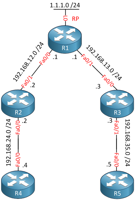
Enough theory. Let’s take a look at the configuration of PIM Bidirectional. I will use the following topology to demonstrate this:
First of all, we will enable unicast and multicast routing on all routers:
R1,R2,R3,R4 and R5:
router ospf 1
network 0.0.0.0 255.255.255.255 area 0
R1,R2,R3,R4 and R5:
ip multicast-routingThe next step is to enable PIM Bidirectional on all PIM-enabled routers:
R1,R2 and R3:
ip pim bidir-enable
Now let’s enable PIM sparse mode on all interfaces:
R1(config)#interface fastEthernet 0/0
R1(config-if)#ip pim sparse-mode
R1(config-if)#interface fastEthernet 0/1
R1(config-if)#ip pim sparse-mode
R1(config-if)#interface loopback0
R1(config-if)#ip pim sparse-modeR2(config)#interface fastEthernet 0/0
R2(config-if)#ip pim sparse-mode
R2(config-if)#interface fastEthernet 0/1
R2(config-if)#ip pim sparse-mode R3(config)#interface fastEthernet 0/0
R3(config-if)#ip pim sparse-mode
R3(config-if)#interface fastEthernet 0/1
R3(config-if)#ip pim sparse-mode The next step is to configure R1 as the RP. We will use the following command on ALL routers:
R1,R2 and R3:
ip pim rp-address 1.1.1.1 bidir
Note that I added the bidir keyword. This is required to allow R1 to be the RP for PIM bidirectional. To keep things simple, I’m statically configuring the RP. You can also use AutoRP, or BSR (Bootstrap). Just don’t forget to add the bidir keyword.
Before we continue, it’s a good idea to check if all routers see R1 as the DR for PIM bidir:
R3#show ip pim rp mapping
PIM Group-to-RP Mappings

Group(s): 224.0.0.0/4, Static, Bidir Mode
    RP: 1.1.1.1 (?)
We can continue if you see that each router sees the RP with Bidir Mode support. If you want, you can check the DF for each segment:
R2#show ip pim interface df
* implies this system is the DF
Interface                RP                DF Winner        Metric     Uptime
FastEthernet0/0          1.1.1.1          *192.168.24.2     11         00:01:36
FastEthernet0/1          1.1.1.1           0.0.0.0          11         01:05:08
Above, you see which router is the DF for each segment. The * indicates that this router is the DF for the given link.
Now let’s generate some traffic!
R4#ping 239.1.1.1 repeat 9999

Type escape sequence to abort.
Sending 9999, 100-byte ICMP Echos to 239.1.1.1, timeout is 2 seconds:
...
We’ll send some pings from R4 to 239.1.1.1. We don’t have any receivers yet, but let’s take a look at the Rendezvous Point:
R1#show ip mroute 239.1.1.1
IP Multicast Routing Table
Flags: D - Dense, S - Sparse, B - Bidir Group, s - SSM Group, C - Connected,
       L - Local, P - Pruned, R - RP-bit set, F - Register flag,
       T - SPT-bit set, J - Join SPT, M - MSDP created entry,
       X - Proxy Join Timer Running, A - Candidate for MSDP Advertisement,
       U - URD, I - Received Source Specific Host Report,
       Z - Multicast Tunnel, z - MDT-data group sender,
       Y - Joined MDT-data group, y - Sending to MDT-data group
Outgoing interface flags: H - Hardware switched, A - Assert winner
 Timers: Uptime/Expires
 Interface state: Interface, Next-Hop or VCD, State/Mode

(*, 239.1.1.1), 00:02:01/00:00:57, RP 1.1.1.1, flags: BP
  Bidir-Upstream: Null, RPF nbr 0.0.0.0
  Outgoing interface list: Null
Above, you see the (*,G) entry for 239.1.1.1. The B flag tells us that this is a PIM Bidirectional group. Let’s configure R5 to join this multicast group:
R5(config)#interface fastEthernet 0/0
R5(config-if)#ip igmp join-group 239.1.1.1
With our pings still running from R4, we’ll take a look at the RP:
R1#show ip mroute 239.1.1.1
IP Multicast Routing Table
Flags: D - Dense, S - Sparse, B - Bidir Group, s - SSM Group, C - Connected,
       L - Local, P - Pruned, R - RP-bit set, F - Register flag,
       T - SPT-bit set, J - Join SPT, M - MSDP created entry,
       X - Proxy Join Timer Running, A - Candidate for MSDP Advertisement,
       U - URD, I - Received Source Specific Host Report,
       Z - Multicast Tunnel, z - MDT-data group sender,
       Y - Joined MDT-data group, y - Sending to MDT-data group
Outgoing interface flags: H - Hardware switched, A - Assert winner
 Timers: Uptime/Expires
 Interface state: Interface, Next-Hop or VCD, State/Mode

(*, 239.1.1.1), 00:02:05/00:03:02, RP 1.1.1.1, flags: B
  Bidir-Upstream: Null, RPF nbr 0.0.0.0
  Outgoing interface list:
    FastEthernet0/1, Forward/Sparse, 00:01:26/00:03:02
The FastEthernet0/1 link toward R3 has been added to the outgoing list. At the Bidir-Upstream, you see Null. This is because the RP is the upstream router. Traffic is streaming from R4 upward the shared tree. We can also take a look at R3 because it’s in the middle of our path:
R3#show ip mroute 239.1.1.1
IP Multicast Routing Table
Flags: D - Dense, S - Sparse, B - Bidir Group, s - SSM Group, C - Connected,
       L - Local, P - Pruned, R - RP-bit set, F - Register flag,
       T - SPT-bit set, J - Join SPT, M - MSDP created entry,
       X - Proxy Join Timer Running, A - Candidate for MSDP Advertisement,
       U - URD, I - Received Source Specific Host Report,
       Z - Multicast Tunnel, z - MDT-data group sender,
       Y - Joined MDT-data group, y - Sending to MDT-data group
Outgoing interface flags: H - Hardware switched, A - Assert winner
 Timers: Uptime/Expires
 Interface state: Interface, Next-Hop or VCD, State/Mode

(*, 239.1.1.1), 00:04:07/00:03:19, RP 1.1.1.1, flags: BC
  Bidir-Upstream: FastEthernet0/0, RPF nbr 192.168.13.1
  Outgoing interface list:
    FastEthernet0/0, Bidir-Upstream/Sparse, 00:04:07/00:00:00
    FastEthernet0/1, Forward/Sparse, 00:04:07/00:03:19
Above, you see that the FastEthernet0/0 interface is the upstream (towards the RP), and FastEthernet0/1 is the outgoing interface (towards R5). Now we will configure R4 to join the 239.1.1.1 multicast group as well so that they can communicate with each other:
R4(config)#interface fastEthernet 0/0
R4(config-if)#ip igmp join-group 239.1.1.1
I’ll send pings from R4 and R5 towards 239.1.1.1:

Hi Rene
First of all thanks a lot or sharing your knowledge. Your way of explanation is very simple & concise. Before start learning any particular topics ya concept, i check ur blog posting includes that topic or not. Jst now i find, Bi Directional PIM. Its so nice to learn from ur blogs. Appreciate the efforts. Thanks a lotzzzzzz…
While labbing the same topology, i found something diff from ur configuration. Here it is:
Then only i am getting the same output as u mention in your most. Let me know i have done mistakes anywhere ya i understood it wrongly.
Hi,
Thanks for the nice article.
Shouldn’t the second-to-last R3 output only show f0/1 in the outgoing interface list? Since R5 is the only receiver?
Hi Paul,
You mean this output?
Rene