Lesson Contents
To understand MPLS there are two questions we need to answer:
- What is MPLS?
- Why do we need MPLS?
I’m going to start this lesson with an explanation of why we need it and how MPLS solves some of the issues of other protocols, this will help you to understand why we use MPLS. In the second part of this lesson you will learn what MPLS is and how it actually works.
When you want to learn MPLS, you need to be very familiar with the following topics before you continue:
- IGPs (like OSPF and EIGRP)
- Tunneling (GRE)
- CEF (Cisco Express Forwarding)
- BGP (Border Gateway Protocol)
Having said that, let’s get started!
Why do we need MPLS?
Take a look at the following picture:
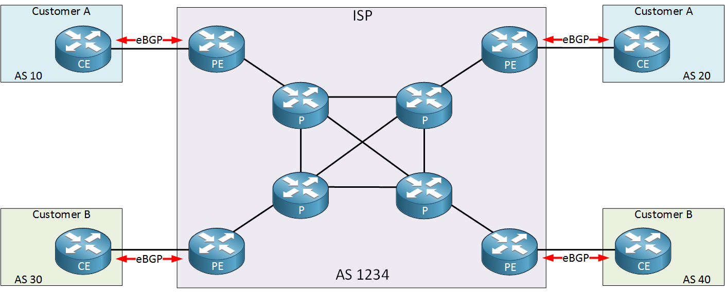
Above we have an example of an ISP with two customers called “A” and “B”. The ISP only offers Internet connectivity and no other services. Each customer uses the ISP to have connectivity between their sites.
To accomplish our goal, the ISP is running eBGP between the CE (Customer Edge) and PE (Provider Edge) to exchange prefixes. This means all internal (P) routers of the ISP have to run iBGP or they don’t know where to forward their packets to.
A full internet routing table currently has > 500.000 prefixes and with 8 ISP routers running iBGP, we need 28 iBGP peerings. We can reduce this number by using route reflectors or a confederation. All routers have to do lookups in the routing table for any possible destination.
Now here’s something to think about…when our goal is to have connectivity between two customer sites, why should all internal P routers know about this? The only routers that need to know how to reach the customer sites are the PE routers of the provider. Why not build a tunnel between the PE routers? Take a look at the picture below:
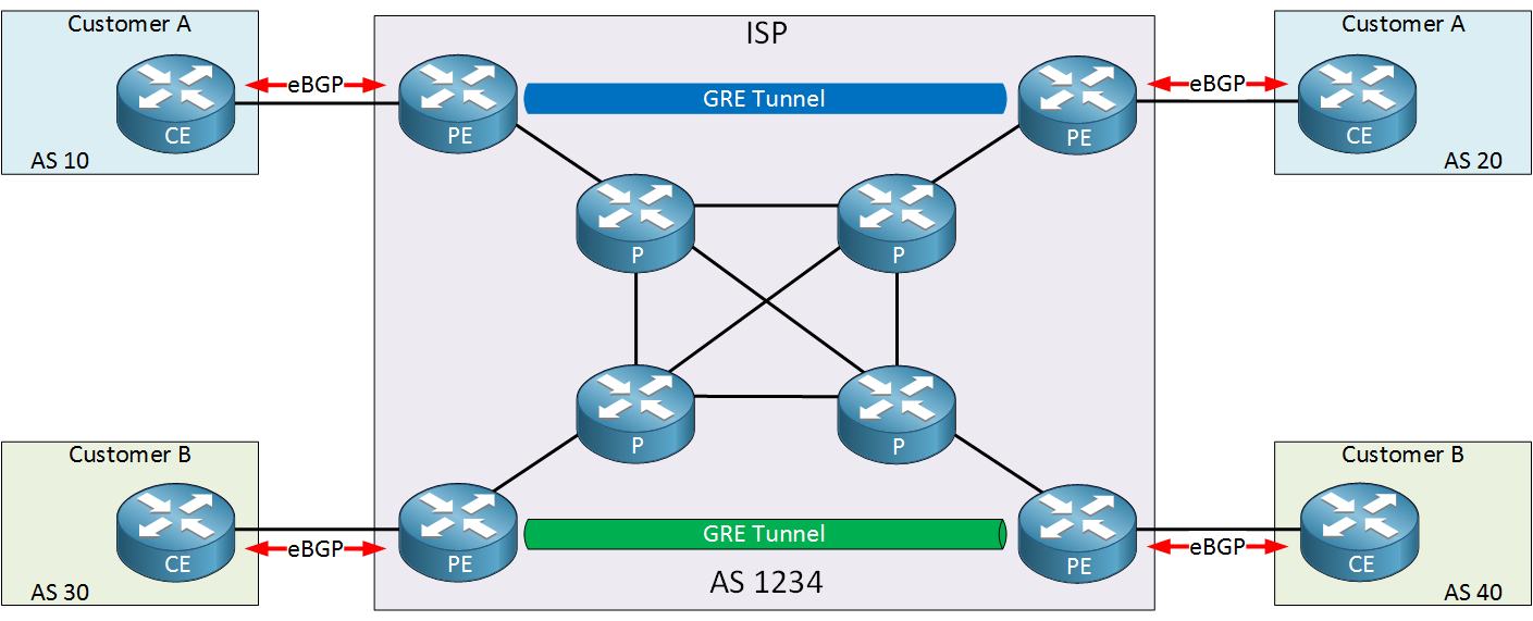
In the picture above I added two GRE tunnels:
- The two PE routers at the top will use a GRE tunnel for the customer A sites.
- The two PE routers at the bottom will use a GRE tunnel for the customer B sites.
With a solution like this, we can have a BGP free core! There’s only two places where we need BGP:
- eBGP between the PE and CE router.
- iBGP between two PE routers.
Let’s take a closer look at the solution I described above.
Tunnel between PE routers
Let’s take a look at the example above in action. I will use the following topology for this:
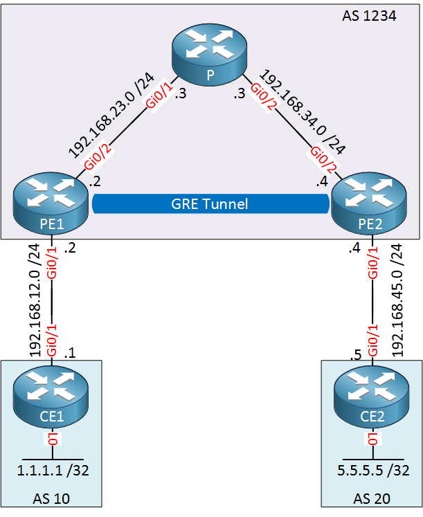
The topology above is a smaller version of the topology I showed you before. This is the ISP with only one customer. We’ll use a GRE tunnel between PE1 and PE2 so that we don’t need iBGP on the P router. Let me walk you through the entire configuration…
OSPF Configuration
First we will configure OSPF on all ISP routes so that PE1 and PE2 are able to reach each other. I’ve added some loopback interfaces on the ISP routers that will be advertised as well:
PE1(config)#router ospf 1
PE1(config-router)#network 192.168.23.0 0.0.0.255 area 0
PE1(config-router)#network 2.2.2.2 0.0.0.0 area 0P(config)#router ospf 1
P(config-router)#network 192.168.23.0 0.0.0.255 area 0
P(config-router)#network 192.168.34.0 0.0.0.255 area 0
P(config-router)#network 3.3.3.3 0.0.0.0 area 0PE2(config)#router ospf 1
PE2(config-router)#network 192.168.34.0 0.0.0.255 area 0
PE2(config-router)#network 4.4.4.4 0.0.0.0 area 0That takes care of all internal routing for the ISP.
eBGP Configuration
Let’s continue by configuring eBGP between the CE and PE routers. We will advertise a loopback on each CE router:
CE1(config)#router bgp 10
CE1(config-router)#neighbor 192.168.12.2 remote-as 1234
CE1(config-router)#network 1.1.1.1 mask 255.255.255.255PE1(config)#router bgp 1234
PE1(config-router)#neighbor 192.168.12.1 remote-as 10PE2(config)#router bgp 1234
PE2(config-router)#neighbor 192.168.45.5 remote-as 20CE2(config)#router bgp 20
CE2(config-router)#neighbor 192.168.45.4 remote-as 1234
CE2(config-router)#network 5.5.5.5 mask 255.255.255.255That takes care of eBGP.
GRE Tunnel Configuration
Now we can configure the GRE tunnel between PE1 and PE2. I will use their loopback interfaces as the source and destination. We will use the 192.168.24.0 /24 subnet on the tunnel interfaces:
PE1(config)#interface tunnel 0
PE1(config-if)#tunnel source 2.2.2.2
PE1(config-if)#tunnel destination 4.4.4.4
PE1(config-if)#ip address 192.168.24.2 255.255.255.0PE2(config)#interface tunnel 0
PE2(config-if)#tunnel source 4.4.4.4
PE2(config-if)#tunnel destination 2.2.2.2
PE2(config-if)#ip address 192.168.24.4 255.255.255.0Now we have a working GRE tunnel.
iBGP Configuration
With the GRE tunnel up and running, we can configure iBGP between the two PE routers:
PE1(config)#router bgp 1234
PE1(config-router)#neighbor 192.168.24.4 remote-as 1234
PE1(config-router)#neighbor 192.168.24.4 next-hop-selfPE2(config)#router bgp 1234
PE2(config-router)#neighbor 192.168.24.2 remote-as 1234
PE2(config-router)#neighbor 192.168.24.2 next-hop-selfOur PE routers will establish an iBGP peering using the IP addresses on the GRE tunnel.
Our configuration is now complete. Let’s find out if it works shall we?
Verification
I’ll do a trace from CE1 to CE2:
CE1#traceroute 5.5.5.5 source loopback 0
Type escape sequence to abort.
Tracing the route to 5.5.5.5
VRF info: (vrf in name/id, vrf out name/id)
  1 192.168.12.2 0 msec 0 msec 0 msec
  2 192.168.24.4 0 msec 0 msec 4 msec
  3 192.168.45.5 0 msec 0 msec *
Great, it’s working! The ISP has a BGP-free core. Here’s what an IP packet from CE1 to CE2 looks like to the P router:
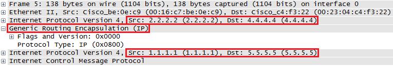
The outer IP header has source address 2.2.2.2 and destination address 4.4.4.4, the P router knows how to route these since it learned these addresses through OSPF.
Configurations
Want to take a look for yourself? Here you will find the final configuration of each device.
CE1
hostname CE1
!
ip cef
!
interface Loopback0
 ip address 1.1.1.1 255.255.255.255
!
interface GigabitEthernet0/1
 ip address 192.168.12.1 255.255.255.0
!
router bgp 10
 bgp log-neighbor-changes
 network 1.1.1.1 mask 255.255.255.255
 neighbor 192.168.12.2 remote-as 1234
!
end
CE2
hostname CE2
!
ip cef
!
interface Loopback0
 ip address 5.5.5.5 255.255.255.255
!
interface GigabitEthernet0/1
 ip address 192.168.45.5 255.255.255.0
!
router bgp 20
 bgp log-neighbor-changes
 network 5.5.5.5 mask 255.255.255.255
 neighbor 192.168.45.4 remote-as 1234
!
control-plane
!
end
P
hostname P
!
ip cef
!
interface Loopback0
 ip address 3.3.3.3 255.255.255.255
!
interface GigabitEthernet0/1
 ip address 192.168.23.3 255.255.255.0
!
interface GigabitEthernet0/2
 ip address 192.168.34.3 255.255.255.0
!
router ospf 1
 network 192.168.23.0 0.0.0.255 area 0
 network 192.168.34.0 0.0.0.255 area 0
!
end
PE1
hostname PE1
!
ip cef
!
interface Loopback0
 ip address 2.2.2.2 255.255.255.255
!
interface Tunnel0
 ip address 192.168.24.2 255.255.255.0
 tunnel source 2.2.2.2
 tunnel destination 4.4.4.4
!
interface GigabitEthernet0/1
 ip address 192.168.12.2 255.255.255.0
!
interface GigabitEthernet0/2
 ip address 192.168.23.2 255.255.255.0
!
router ospf 1
 network 2.2.2.2 0.0.0.0 area 0
 network 192.168.23.0 0.0.0.255 area 0
!
router bgp 1234
 bgp log-neighbor-changes
 neighbor 192.168.12.1 remote-as 10
 neighbor 192.168.24.4 remote-as 1234
 neighbor 192.168.24.4 next-hop-self
!
end
PE2
hostname PE2
!
ip cef
!
interface Loopback0
 ip address 4.4.4.4 255.255.255.255
!
interface Tunnel0
 ip address 192.168.24.4 255.255.255.0
 tunnel source 4.4.4.4
 tunnel destination 2.2.2.2
!
interface GigabitEthernet0/1
 ip address 192.168.45.4 255.255.255.0
!
interface GigabitEthernet0/2
 ip address 192.168.34.4 255.255.255.0
!
router ospf 1
 network 4.4.4.4 0.0.0.0 area 0
 network 192.168.34.0 0.0.0.255 area 0
!
router bgp 1234
 bgp log-neighbor-changes
 neighbor 192.168.24.2 remote-as 1234
 neighbor 192.168.24.2 next-hop-self
 neighbor 192.168.45.5 remote-as 20
!
end
Great! Now you might be thinking…so what? Where’s MPLS?
For now, keep in mind that tunneling is used to create a BGP free core. Hold this thought while you read the next section of this lesson where we finally start talking about MPLS!
What is MPLS?
In the previous example I used a GRE tunnel but I could have used any tunneling mechanism. Besides GRE, there’s IP-in-IP, Q-in-Q and…
MPLS (Multi Protocol Label Switching).
What does multi protocol label switching mean?
- Multi protocol: besides IP you can tunnel pretty much anything…IP, IPv6, Ethernet, PPP, frame-relay, etc.
- Label switching: forwarding is done based on labels, not by looking up the destination in the routing table.
MPLS can do anything that any of the other tunneling protocols support and it can do a lot more than that.
Let’s start with something simple, let’s replace the GRE tunnel from the previous example with MPLS so I can explain how MPLS uses labels.
First let’s get rid of the GRE tunnel and the BGP peering between PE1 and PE2:
PE1 & PE2
(config)#no interface tunnel 0PE1(config)#router bgp 1234
PE1(config-router)#no neighbor 192.168.24.4 remote-as 1234PE2(config)#router bgp 1234
PE2(config-router)#no neighbor 192.168.24.2 remote-as 1234Now we can start with the MPLS configuration.
iBGP configuration
Once again I will configure iBGP between PE1 and PE2 but this time I will use their loopback interfaces. You will see why in a minute:
PE1(config)#router bgp 1234
PE1(config-router)#neighbor 4.4.4.4 remote-as 1234
PE1(config-router)#neighbor 4.4.4.4 update-source loopback 0
PE1(config-router)#neighbor 4.4.4.4 next-hop-selfPE2(config)#router bgp 1234
PE2(config-router)#neighbor 2.2.2.2 remote-as 1234
PE2(config-router)#neighbor 2.2.2.2 update-source loopback 0
PE2(config-router)#neighbor 2.2.2.2 next-hop-self That takes care of iBGP.
MPLS Configuration
This is the exciting part, let’s enable MPLS. We’ll do this on all interfaces that connect PE1, PE2 and the P router:
PE1(config)#interface GigabitEthernet 0/2
PE1(config-if)#mpls ipP(config)#interface GigabitEthernet 0/1
P(config-if)#mpls ipP(config)#interface GigabitEthernet 0/2
P(config-if)#mpls ipPE2(config)#interface GigabitEthernet 0/2
PE2(config-if)#mpls ipThat’s pretty simple…only one command to activate MPLS on our interfaces. In the next lesson I will explain what exactly happens when you use this command, for now I want to focus on the labels.
Verification
Let’s try a quick ping between CE1 and CE2:
CE1#ping 5.5.5.5 source loopback 0
Type escape sequence to abort.
Sending 5, 100-byte ICMP Echos to 5.5.5.5, timeout is 2 seconds:
Packet sent with a source address of 1.1.1.1
!!!!!
Success rate is 100 percent (5/5), round-trip min/avg/max = 1/2/4 ms
Great, it works. Why does it work? Keep in mind there is no iBGP on the P router:
P#show ip cef 5.5.5.5
0.0.0.0/0
  no route
Normally this traffic should be dropped since this router has no idea how it can reach 5.5.5.5. However, since we enabled MPLS we are now using labels for our forwarding decisions. Let me explain how that works.
Let’s start with PE1:
PE1#show ip route 5.5.5.5
Routing entry for 5.5.5.5/32
  Known via "bgp 1234", distance 200, metric 0
  Tag 5, type internal
  Last update from 4.4.4.4 00:20:16 ago
  Routing Descriptor Blocks:
  * 4.4.4.4, from 4.4.4.4, 00:20:16 ago
      Route metric is 0, traffic share count is 1
      AS Hops 1
      Route tag 5
      MPLS label: none
To reach 5.5.5.5, we have to use 4.4.4.4 as the next hop. Instead of checking the routing table, let’s take a look at the MPLS forwarding table:
PE1#show mpls forwarding-table
Local      Outgoing   Prefix           Bytes Label   Outgoing   Next Hop
Label      Label      or Tunnel Id     Switched      interface
16         17         4.4.4.4/32       0             Gi0/2      192.168.23.3
17         Pop Label  192.168.34.0/24  0             Gi0/2      192.168.23.3
18         Pop Label  3.3.3.3/32       0             Gi0/2      192.168.23.3
Above you can see the labels that this router uses to reach certain prefixes. In the next lesson we’ll discuss how these labels are generated. To reach 4.4.4.4, this router will add label 17 to the IP packet and forwards it on GigabitEthernet 0/2 (towards the P router). A quicker method to see what labels are used for different prefixes is by checking the CEF table:
PE1#show ip cef 5.5.5.5
5.5.5.5/32
  nexthop 192.168.23.3 GigabitEthernet0/2 label 17
Here’s a capture of the IP packet that PE1 sends to the P router:
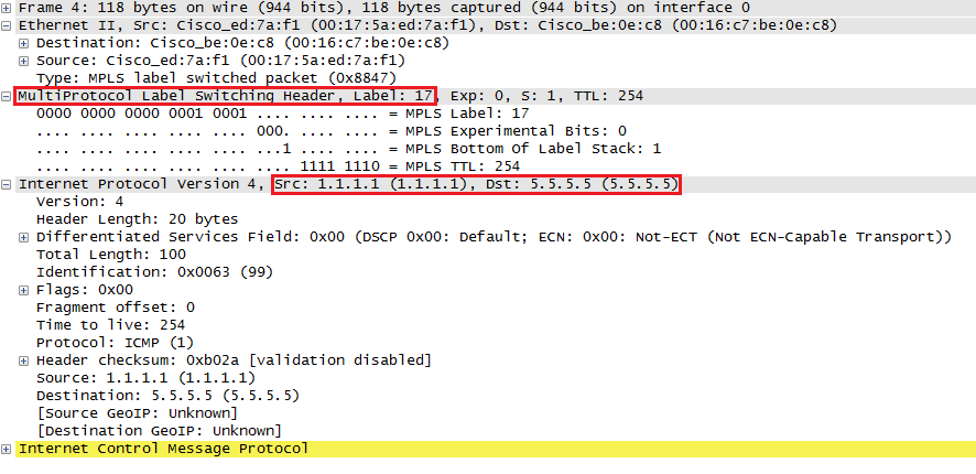
You can see that the MPLS header has been added in between the Ethernet and IP header. This is why they call MPLS a layer 2.5 protocol.
So what happens when the P router receives this IP packet? It’s using MPLS for forwarding decisions so let’s take a look at its labels:
P#show mpls forwarding-table
Local      Outgoing   Prefix           Bytes Label   Outgoing   Next Hop
Label      Label      or Tunnel Id     Switched      interface
16         Pop Label  2.2.2.2/32       152492        Gi0/1      192.168.23.2
17         Pop Label  4.4.4.4/32       153234        Gi0/2      192.168.34.4
When the P router receives something that is tagged with label 17, then it has to be forwarded to 4.4.4.4. It’s outgoing label says “pop label” which means to remove the label.
PE2 will receive a regular IP packet (without label) with destination 5.5.5.5 and it will forward it using the routing table towards CE2.
When CE2 receives the packet, it will create an ICMP echo reply which will end up at PE2. Here’s what PE2 will do with it:
PE2#show ip route 1.1.1.1
Routing entry for 1.1.1.1/32
  Known via "bgp 1234", distance 200, metric 0
  Tag 1, type internal
  Last update from 2.2.2.2 00:31:34 ago
  Routing Descriptor Blocks:
  * 2.2.2.2, from 2.2.2.2, 00:31:34 ago
      Route metric is 0, traffic share count is 1
      AS Hops 1
      Route tag 1
      MPLS label: none
PE2 knows that it has to use next hop 2.2.2.2 to reach 1.1.1.1. Let’s check what label we will use to reach 2.2.2.2:
PE2#show mpls forwarding-table
Local      Outgoing   Prefix           Bytes Label   Outgoing   Next Hop
Label      Label      or Tunnel Id     Switched      interface
16         16         2.2.2.2/32       0             Gi0/2      192.168.34.3
17         Pop Label  192.168.23.0/24  0             Gi0/2      192.168.34.3
18         Pop Label  3.3.3.3/32       0             Gi0/2      192.168.34.3
PE2 will add label 16 to the IP packet and will forward it out the GigabitEthernet 0/2 interface towards the P router. Looking at the CEF table is a quicker method to find the label for a destination prefix:
PE2#show ip cef 1.1.1.1
1.1.1.1/32
  nexthop 192.168.34.3 GigabitEthernet0/2 label 16
The PE2 router will forward it to the P router. Let’s check what it will do with this packet:
P#show mpls forwarding-table
Local      Outgoing   Prefix           Bytes Label   Outgoing   Next Hop
Label      Label      or Tunnel Id     Switched      interface
16         Pop Label  2.2.2.2/32       154767        Gi0/1      192.168.23.2
17         Pop Label  4.4.4.4/32       155528        Gi0/2      192.168.34.4
Router P sees that anything with label 16 should be forwarded on the GigabitEthernet 0/1 interface. It will remove the label and forwards it to PE1.
PE1 can then forward the IP packet (without label) using its routing table to CE1.
That’s how we use MPLS to tunnel traffic between PE routers, creating a BGP free core.
Configurations
Want to take a look for yourself? Here you will find the startup configuration of each device.
CE1
hostname CE1
!
ip cef
!
interface Loopback0
 ip address 1.1.1.1 255.255.255.255
!
interface GigabitEthernet0/1
 ip address 192.168.12.1 255.255.255.0
!
router bgp 10
 bgp log-neighbor-changes
 network 1.1.1.1 mask 255.255.255.255
 neighbor 192.168.12.2 remote-as 1234
!
end
CE2
hostname CE2
!
ip cef
!
interface Loopback0
 ip address 5.5.5.5 255.255.255.255
!
interface GigabitEthernet0/1
 ip address 192.168.45.5 255.255.255.0
!
router bgp 20
 bgp log-neighbor-changes
 network 5.5.5.5 mask 255.255.255.255
 neighbor 192.168.45.4 remote-as 1234
!
end
P
hostname P
!
ip cef
!
interface Loopback0
 ip address 3.3.3.3 255.255.255.255
!
interface GigabitEthernet0/1
 ip address 192.168.23.3 255.255.255.0
 mpls ip
!
interface GigabitEthernet0/2
 ip address 192.168.34.3 255.255.255.0
 mpls ip
!
router ospf 1
 network 3.3.3.3 0.0.0.0 area 0
 network 192.168.23.0 0.0.0.255 area 0
 network 192.168.34.0 0.0.0.255 area 0
!
end
PE1
hostname PE1
!
ip cef
!
interface Loopback0
 ip address 2.2.2.2 255.255.255.255
!
interface GigabitEthernet0/1
 ip address 192.168.12.2 255.255.255.0
!
interface GigabitEthernet0/2
 ip address 192.168.23.2 255.255.255.0
 mpls ip
!
router ospf 1
 network 2.2.2.2 0.0.0.0 area 0
 network 192.168.23.0 0.0.0.255 area 0
!
router bgp 1234
 bgp log-neighbor-changes
 neighbor 4.4.4.4 remote-as 1234
 neighbor 4.4.4.4 update-source Loopback0
 neighbor 4.4.4.4 next-hop-self
 neighbor 192.168.12.1 remote-as 10
!
end
PE2
hostname PE2
!
ip cef
!
interface Loopback0
 ip address 4.4.4.4 255.255.255.255
!
interface GigabitEthernet0/1
 ip address 192.168.45.4 255.255.255.0
!
interface GigabitEthernet0/2
 ip address 192.168.34.4 255.255.255.0
 mpls ip
!
router ospf 1
 network 4.4.4.4 0.0.0.0 area 0
 network 192.168.34.0 0.0.0.255 area 0
!
router bgp 1234
 bgp log-neighbor-changes
 neighbor 2.2.2.2 remote-as 1234
 neighbor 2.2.2.2 update-source Loopback0
 neighbor 2.2.2.2 next-hop-self
 neighbor 192.168.45.5 remote-as 20
!
end
Conclusion
I hope this lesson has been useful to get a basic understanding of why we use MPLS and how it uses labels as a tunneling mechanism to create a BGP free core. There’s a lot more to this story. In other lessons you will learn:
- How MPLS routers generate/exchange labels using LDP.
- How to build MPLS VPNs
- How to tunnel Ethernet or frame-relay over your MPLS network.
- And more…
If you have any questions, feel free to leave a comment in our forum.
I am a bit confused when you say “BGP free core”. If we are using iBGP between the PE routers then how can it still be a BGP free core? Or does this simply mean there is no BGP process running on the ‘P’ router?
Hi Emir,
That’s right, the P routers form the “core” of the ISP network. Only the PE (provider edge) routers will require iBGP.
Rene
Great, thanks.
Good mpls intro,thanks Rene! , i will lab this one for sure
Trying this yourself is a good idea Tomorrow I’ll work on the MPLS LDP tutorial, that will explain where the labels come etc.