Lesson Contents
IPSec VTIs (Virtual Tunnel Interface) is a newer method to configure site-to-site IPSec VPNs. It’s a simpler method to configure VPNs, it uses a tunnel interface, and you don’t have to use any pesky access-lists and a crypto-map anymore to define what traffic to encrypt.
Configuration
Let’s look at an example. I use the following topology:
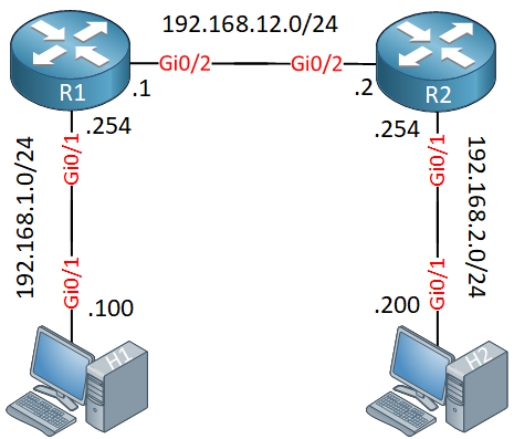
R1 and R2 are the two routers that will be used for the site-to-site IPSec VPN. I will manually configure the tunnel and endpoints, so this will be a static virtual tunnel interface. H1 and H2 are used to test the tunnel.
Let’s start with R1:
R1
Let’s start with the IPSec phase 1 configuration:
R1(config)#crypto isakmp policy 1
R1(config-isakmp)#encryption aes
R1(config-isakmp)#authentication pre-share
R1(config-isakmp)#group 2
And configure our remote neighbor (R2):
R1(config-isakmp)#crypto isakmp key MY_PASSWORD address 192.168.12.2Now we can configure phase 2:
R1(config)#crypto ipsec transform-set MY_TRANSFORM_SET esp-aes esp-sha-hmac
R1(cfg-crypto-trans)#mode tunnelR1(config)#crypto ipsec profile IPSEC_PROFILE
R1(ipsec-profile)#set transform-set MY_TRANSFORM_SETThis part is much simpler…you only have to create a transform-set and a crypto IPSec profile. The crypto IPSec profile refers to the transform-set. You don’t have to create a crypto-map anymore and apply it to the outside interface.
Now we combine everything on the tunnel interface:
R1(config)#interface Tunnel 0
R1(config-if)#ip address 12.12.12.1 255.255.255.0
R1(config-if)#tunnel source 192.168.12.1
R1(config-if)#tunnel destination 192.168.12.2
R1(config-if)#tunnel mode ipsec ipv4
R1(config-if)#tunnel protection ipsec profile IPSEC_PROFILE
The configuration of the tunnel interface is similar to a regular GRE tunnel. We set a source and destination IP address. The tunnel mode, however, is IPSec IPv4 and we have to add our IPSec profile.
Last but not least, make sure you have a route that points to the subnet on the other side. The destination is the tunnel interface:
R1(config)#ip route 192.168.2.0 255.255.255.0 Tunnel0That’s all we need.
R2
The configuration of R2 is exactly the same except for the IP addresses:
R2(config)#crypto isakmp policy 1
R2(config-isakmp)# encryption aes
R2(config-isakmp)# authentication pre-share
R2(config-isakmp)# group 2R2(config-isakmp)#crypto isakmp key MY_PASSWORD address 192.168.12.1 R2(config)#crypto ipsec transform-set MY_TRANSFORM_SET esp-aes esp-sha-hmac
R2(cfg-crypto-trans)# mode tunnelR2(config)#crypto ipsec profile IPSEC_PROFILE
R2(ipsec-profile)# set transform-set MY_TRANSFORM_SET R2(config)#interface Tunnel0
R2(config-if)# ip address 12.12.12.2 255.255.255.0
R2(config-if)# tunnel source 192.168.12.2
R2(config-if)# tunnel destination 192.168.12.1
R2(config-if)# tunnel mode ipsec ipv4
R2(config-if)# tunnel protection ipsec profile IPSEC_PROFILER2(config)#ip route 192.168.1.0 255.255.255.0 Tunnel0That’s all there is to it.
Verification
Let’s see if this works! We will start with a quick ping:
H1#ping 192.168.2.200
Type escape sequence to abort.
Sending 5, 100-byte ICMP Echos to 192.168.2.200, timeout is 2 seconds:
!!!!!
Success rate is 100 percent (5/5), round-trip min/avg/max = 18/24/37 ms
This ping is promising. Remember that the static routes on R1 and R2 point to the tunnel interface so this at least tells me it’s probably working. Let’s take a closer look at the tunnel interface:
R1#show interfaces Tunnel 0
Tunnel0 is up, line protocol is up
  Hardware is Tunnel
  Internet address is 12.12.12.1/24
  MTU 17878 bytes, BW 100 Kbit/sec, DLY 50000 usec,
     reliability 255/255, txload 1/255, rxload 1/255
  Encapsulation TUNNEL, loopback not set
  Keepalive not set
  Tunnel linestate evaluation up
  Tunnel source 192.168.12.1, destination 192.168.12.2
  Tunnel protocol/transport IPSEC/IP
  Tunnel TTL 255
  Tunnel transport MTU 1438 bytes
  Tunnel transmit bandwidth 8000 (kbps)
  Tunnel receive bandwidth 8000 (kbps)
  Tunnel protection via IPSec (profile "IPSEC_PROFILE")
The output above is useful. It tells me the tunnel interface is up and running, that it’s using IPSec and it shows us the IPSec profile. Let’s take a closer look at the IPSec session:

In my lab , GNS3, running the command “tunnel mode ipsec ipv4” actually breaks VTI. I am unable to pass traffic . Once i remove that piece and keep the tunnel protection command then my VPN comes up. Do you know why?
I am running C7200-ADVENTERPRISEK9-M code.
Running a packet capture i see that traffic is indeed encrypted (ESP) over my “wan”.
Hi Michael,
I haven’t seen that before. If you enable a debug, does anything come up?
Rene
Hi Rene
If i have 3 routers and like A B C and i want to create IPsec Virtual Tunnel Interface between A and C. As i see your configuration.
In my case I have router B in the middle so tunnel source and tunnel destination will not be in the same network. Is it ok about that ?
Thank u.
Sovandara
Hi Sovandara,
If you want to establish a tunnel between R1 and R3, you would use 192.168.12.1 and 192.168.23.3 as the source and destination addresses.
Hi Rene
Do you plan on doing a dynamic example also, using Virtual Access and Virtual Templates?