Lesson Contents
We used Cisco’s three-layer hierarchical architecture for more than a decade, but in data centers, the spine-leaf architecture is more popular nowadays. In this lesson, you will learn about the spine-leaf architecture and its advantages.
Before we do that, you need to understand how data centers evolved and the disadvantages of the three-layer hierarchical architecture.
Data Center Evolution
Let’s start with a short history lesson of how the three-layer architecture evolved throughout the years.
Three-layer hierarchical architecture
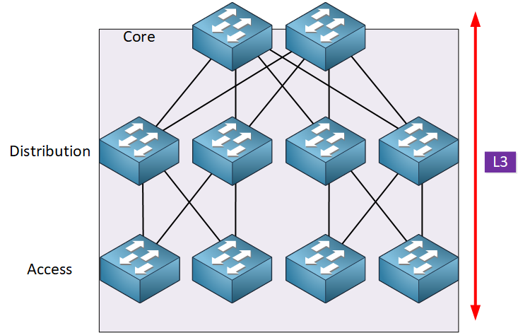
Here’s an overview of the three-layer model:
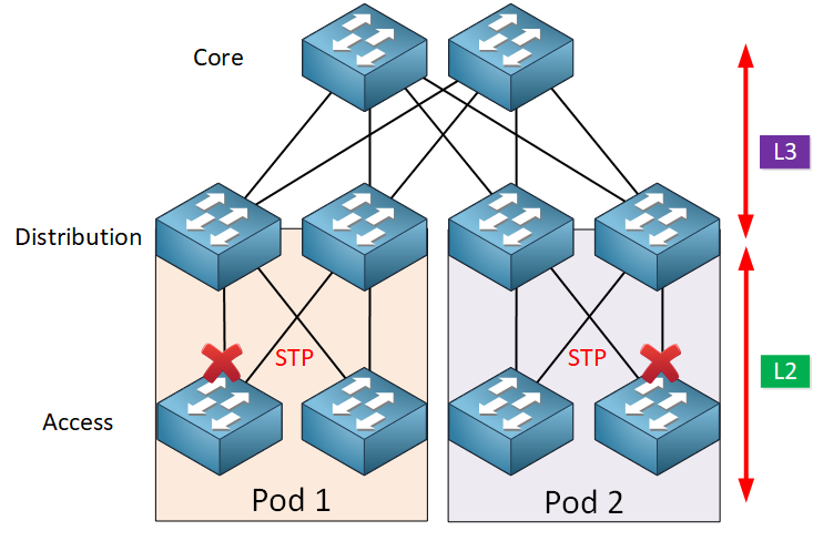
For over a decade, we used this architecture with the three layers:
- Core
- Distribution (aggregation)
- Access
The access layer is where we connect our end devices. In a campus network, these are usually computers, laptops, and access points. In a data center, this is where our servers are. The distribution layer has redundant connections to access layer switches and connects to the core layer. The core layer provides fast transport between distribution layer switches.
Between the access layer and the distribution layer, we use L2 and spanning tree (STP) to block all links except one. Between the distribution and core layer, we use routing.
For a detailed explanation, you can take a look at the campus network design lesson.
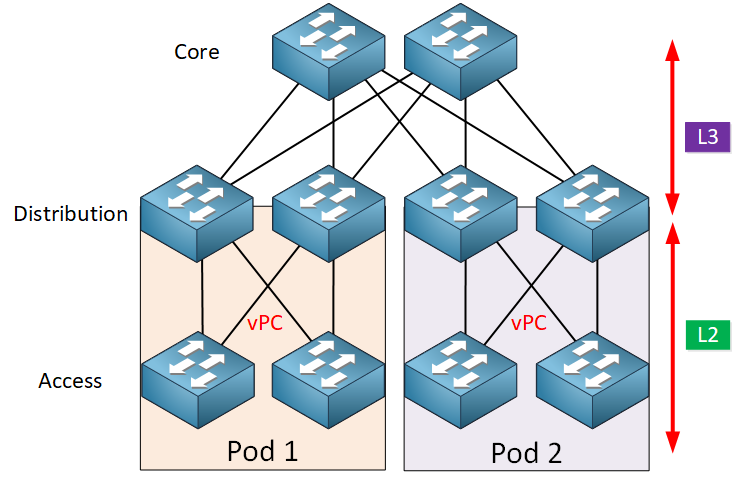
vPC
To overcome the limitations of STP, Cisco introduced virtual-port-channels (vPC) in 2010. vPCs offer active-active uplinks from the access layer switches to the distribution layer switches. vPCs allow us to use all available bandwidth.
L2 Topology
Because of virtualization, we can now pool the computing, networking, and storage resources in a pod into virtual resources. Pooling these resources often requires large L2 domains that span from the access layer up to the core layer.
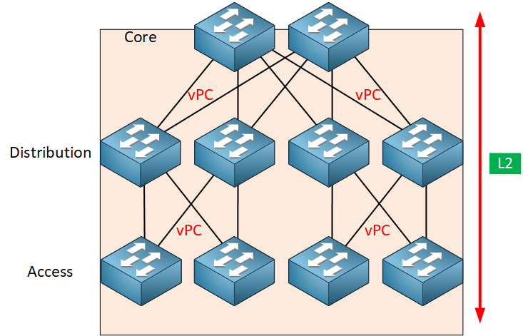
With these large L2 domains that span across the entire network, we can create a flexible resource pool and reallocate resources where needed.
An example is our servers. Before virtualization, we had physical servers in a single pod. With virtualization, we have hypervisors in multiple pods. A virtual machine that runs on a hypervisor in pod one can move to a hypervisor in pod two without any downtime. VMWare’s VMotion can do this but requires L2 connectivity to do it.
A side effect of having resources spread out over the network instead of within a single pod is that the amount of east-west traffic increases.
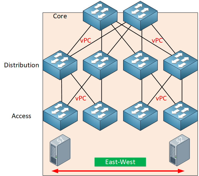
Traffic between the two servers has to go through all layers of our network.
L3 Topology
Another option is to use routing everywhere. The advantages of a routed topology are that we can use all links for forwarding and routing protocols converge faster than STP. If we require L2 connectivity between servers in different pods, we can use a VXLAN overlay network if needed.
Advantages and disadvantages
The three-layer hierarchical architecture has some advantages and disadvantages. Let’s take a look.
Advantages
This model offers the following advantages:
- Availability: When a pod goes down, the issue is usually isolated to one pod and doesn’t affect other pods.
- Security: We use L2 between the access and distribution layers and L3 between the distribution layers and core layer. We can filter traffic on L3 so we can decide what traffic goes into or outside of a pod.
- Scalability: When the network grows, we can easily add more distribution or access layer switches.
- Familiarity: We used this model for over a decade, so network engineers are familiar with this design and the protocols we use.
Disadvantages
There are, however, some disadvantages, which is why the spine-leaf architecture is gaining popularity.
Here are two important disadvantages:
- Limited bandwidth: vPCs solve the STP problem that we can only use one active link, but vPCs are limited to two active uplinks.
- Latency: The server-to-server latency could be high, depending on the traffic path. East-west traffic between pods has to go through the distribution and core layers.
Spine and Leaf Architecture
The spine-leaf architecture was developed to overcome the limitations of the three-tier architecture. It offers high bandwidth, low latency, and non-blocking server-to-server connectivity for data centers that primarily have east-west traffic flows. Here’s what it looks like:

Hi Rene, excellent post. I have a question regarding vPC on your Conclusions, “vPC somehow solves this limitation of STP, but vPC can only use two active links.” - what do you mean by “only use two active links”?
Hello Laura
When configuring vPC peers, you can only connect to two devices. Specifically, Cisco states:
Note some invalid configurations below:
https://cdn-forum.networklessons.com/uploads/default/original/2X/3/32d2546787ce45ad6d8c2c11b706c587169f833b.png
You can find out more info at this Cisco documentation:https://www.cisco.com/c/en/us/td/docs/switches/datacenter/nexus9000/sw/6-x/i
... Continue reading in our forumHi guys
I think you don’t get Laura’s point- you can only connect 1 switch to 2 vpc peers , but that does not mean you only can have 1 uplink to each peer.
We have in our datacenter configured some switches with 8 uplinks to each 5k nexus, so you have 8 links participating in 1 vpc
The picture you showed is for 1 switch connecting to 3 vpc peers - that is not possible, but 1 device connected to 2 vpc peers using 8 links on switch and 4 on each vpc peer is doable and frequently used
Hello Marek
Yes, thanks for the clarification. It is true that you can have each individual uplink to a peer be composed of an etherchannel, so that you can have up to 8 physical links to each of the vPC peers. That way you can have up to 16 physical links.
However, the limitation that Rene was speaking about in the lesson is the fact that you are limited to uplinks to a maximum of two vPC peers. You cannot have uplinks to more than two physical switches like you can with spine and leaf.
I hope this has been helpful!
Laz
Hi,
If we have spine and leaf architecture , where do we place firewall ?
Thanks