Lesson Contents
Frame-relay requires a frame-relay switch that “switches” one DLCI to another, creating a virtual circuit. Normally you don’t really have to think about the frame-relay switch since this is something that the service provider will configure. If you are studying frame-relay for (Cisco) exams then you only need to understand how to configure it from the customer’s perspective.
If you want to configure frame-relay in your lab then you do require a frame-relay switch. Luckily for us, it’s possible to configure a Cisco router as a frame-relay switch. That’s what we will do this in this lesson. Take a look at the following picture:
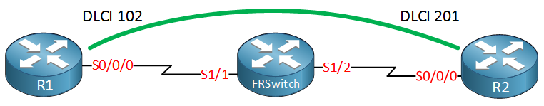
Above we have three routers, we want to create a PVC between R1 and R2. The router in the middle will be our frame-relay switch.
Configuration
Let’s start with the frame-relay switch. The first thing we need to do is enable frame-relay switching globally:
FRSWITCH(config)#frame-relay switchingNow we can focus on the interface configuration:
FRSWITCH(config)#interface serial1/1
FRSWITCH(config-if)#description R1
FRSWITCH(config-if)#clock rate 128000
Make sure you have a clock rate configured on DCE interfaces. This is not related to frame-relay directly but it is required for serial interfaces and easily overlooked. Now we can configure some frame-relay specific commands:
FRSWITCH(config-if)#encapsulation frame-relay
FRSWITCH(config-if)#frame-relay intf-type dce
FRSWITCH(config-if)#frame-relay route 102 interface serial1/2 201
There are three frame-relay specific commands that we configured:
- We need to enable frame-relay encapsulation.
- The interface has to be configured as frame-relay DCE.
- We tell the interface to switch everything that arrives as DLCI 102 to interface S1/2 as DLCI 201.
Let’s configure the interface that connects to R2 as well:
FRSWITCH(config)#interface serial1/2
FRSWITCH(config-if)#clock rate 128000
FRSWITCH(config-if)#description R2
FRSWITCH(config-if)#encapsulation frame-relay
FRSWITCH(config-if)#frame-relay intf-type dce
FRSWITCH(config-if)#frame-relay route 201 interface serial1/1 102
The configuration above is the same except the frame-relay route command is in reverse. The only thing left to do know is to enable the interfaces of R1 and R2:
R1(config)#interface serial 0/0/0
R1(config-if)#encapsulation frame-relayR2(config)#interface Serial 0/0/0
R2(config-if)#encapsulation frame-relayEverything is now in place, let’s check if the PVCs are up and running. We can check this with the following command:
FRSWITCH#show frame-relay route
Input Intf      Input Dlci      Output Intf     Output Dlci     Status
Serial1/1       102             Serial1/2       201             active
Serial1/2       201             Serial1/1       102             active
Above you can see that the PVC is active. Let’s verify this on R1 and R2:
R1#show frame-relay pvc

PVC Statistics for interface Serial0/0/0 (Frame Relay DTE)

              Active     Inactive      Deleted       Static
  Local          0            0            0            0
  Switched       0            0            0            0
  Unused         1            0            0            0

DLCI = 102, DLCI USAGE = UNUSED, PVC STATUS = ACTIVE, INTERFACE = Serial0/0/0

  input pkts 0             output pkts 0            in bytes 0
  out bytes 0              dropped pkts 0           in pkts dropped 0
  out pkts dropped 0                out bytes dropped 0
  in FECN pkts 0           in BECN pkts 0           out FECN pkts 0
  out BECN pkts 0          in DE pkts 0             out DE pkts 0
  out bcast pkts 0         out bcast bytes 0
  5 minute input rate 0 bits/sec, 0 packets/sec
  5 minute output rate 0 bits/sec, 0 packets/sec
pvc create time 00:00:25, last time pvc status changed 00:00:25R2#show frame-relay pvc
PVC Statistics for interface Serial0/0/0 (Frame Relay DTE)
Active Inactive Deleted Static
Local 0 0 0 0
Switched 0 0 0 0
Unused 1 0 0 0
DLCI = 201, DLCI USAGE = UNUSED, PVC STATUS = ACTIVE, INTERFACE = Serial0/0/0
input pkts 0 output pkts 0 in bytes 0
out bytes 0 dropped pkts 0 in pkts dropped 0
out pkts dropped 0 out bytes dropped 0
in FECN pkts 0 in BECN pkts 0 out FECN pkts 0
out BECN pkts 0 in DE pkts 0 out DE pkts 0
out bcast pkts 0 out bcast bytes 0
5 minute input rate 0 bits/sec, 0 packets/sec
5 minute output rate 0 bits/sec, 0 packets/sec
pvc create time 00:00:38, last time pvc status changed 00:00:38Excellent our PVC is up and running. The frame-relay hub and spoke topology is the most popular one so let’s add one more router to our network:
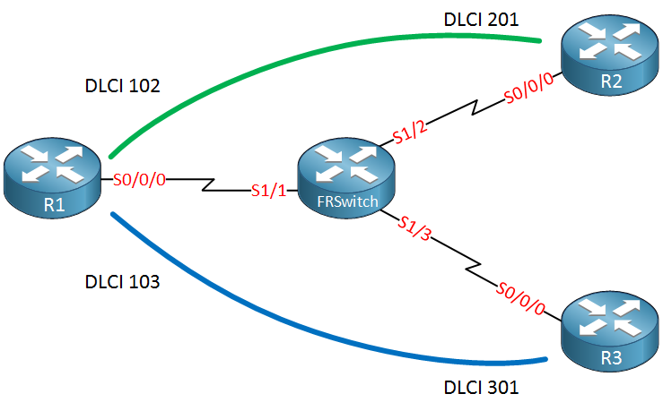
Above we have added R3 and a second PVC between R1 and R3. Let’s configure the frame-relay switch:
FRSWITCH(config)#interface Serial 1/1
FRSWITCH(config-if)#frame-relay route 103 interface Serial 1/3 301
We already configured the interface that connects to R1 so the only thing left to do is to add another frame-relay route. Let’s configure S1/3 that connects to R3:
FRSWITCH(config)#interface Serial 1/3
FRSWITCH(config-if)#description R3
FRSWITCH(config-if)#encapsulation frame-relay
FRSWITCH(config-if)#clock rate 128000
FRSWITCH(config-if)#frame-relay intf-type dce
FRSWITCH(config-if)#frame-relay route 301 interface Serial 1/1 103
Let’s enable frame-relay encapsulation on R3:
R3(config)#interface Serial 0/0/0
R3(config-if)#encapsulation frame-relay
And verify our work on the frame-relay switch:
FRSWITCH#show frame-relay route
Input Intf      Input Dlci      Output Intf     Output Dlci     Status
Serial1/1       102             Serial1/2       201             active
Serial1/1       103             Serial1/3       301             active
Serial1/2       201             Serial1/1       102             active
Serial1/3       301             Serial1/1       103             active
The new PVC is active, let’s also check it on the routers:
R1#show frame-relay pvc | include PVC
PVC Statistics for interface Serial0/0/0 (Frame Relay DTE)
DLCI = 102, DLCI USAGE = UNUSED, PVC STATUS = ACTIVE, INTERFACE = Serial0/0/0
DLCI = 103, DLCI USAGE = UNUSED, PVC STATUS = ACTIVE, INTERFACE = Serial0/0/0R2#show frame-relay pvc | include PVC
PVC Statistics for interface Serial0/0/0 (Frame Relay DTE)
DLCI = 201, DLCI USAGE = UNUSED, PVC STATUS = ACTIVE, INTERFACE = Serial0/0/0R3#show frame-relay pvc | include PVC
PVC Statistics for interface Serial0/0/0 (Frame Relay DTE)
DLCI = 301, DLCI USAGE = UNUSED, PVC STATUS = ACTIVE, INTERFACE = Serial0/0/0The routers also see the PVC as active.
Everything is now up and running, the frame-relay layer two configuration is now complete.
Configurations
Want to take a look for yourself? Here you will find the final configuration of each device.
R1
Hostname R1
!
interface Serial0/1/0
 no ip address
 encapsulation frame-relay
!
end
R2
Hostname R2
!
interface Serial0/1/0
 no ip address
 encapsulation frame-relay
!
end
R3
Hostname R3
!
interface Serial0/1/0
 no ip address
 encapsulation frame-relay
!
end
FRSWITCH
hostname FRSWITCH
!
frame-relay switching
!
interface Serial1/1
 description R1
 no ip address
 encapsulation frame-relay
 clock rate 128000
 frame-relay intf-type dce
 frame-relay route 102 interface Serial1/2 201
 frame-relay route 103 interface Serial1/3 301
!
interface Serial1/2
 description R2
 no ip address
 encapsulation frame-relay
 clock rate 128000
 frame-relay intf-type dce
 frame-relay route 201 interface Serial1/1 102
!
interface Serial1/3
 no ip address
 encapsulation frame-relay
 clock rate 128000
 frame-relay intf-type dce
 frame-relay route 301 interface Serial1/1 103
!
end
Conclusion
Configuring a frame-relay switch is not something you’ll have to do often but when you need one, you now know how to configure one on your Cisco router. Any questions? feel free to leave a comment in our forum.
What happens to a dlci when it goes through a router? is this layer 2 from ISP to your remote site?
Hello Justin,
As I was writing you answer I found that I need some deeper understanding of this topic myself. What I can say is that Rene has an excellent analogy for this.
https://networklessons.com/frame-relay/introduction-to-frame-relay-for-ccna-students/
This lesson may help you understand the topic better. I would dive into this lesson myself but I have just finished studying and need a break. Please let me know if I can help you on these forums!
I hope this helps,
Scott
Thanks for the link. I have read this article multiple times =)
Hello Justin
Frame relay is a layer two technology and as a result, DLCIs do not traverse a router. In this example, the Frame Relay Switch is actually physically a router, a layer three device, but its functionality in this case is a layer two device. This can be seen clearly by the encapsulation of type “frame relay” that is specified in the config. Specifically it is switching between one DLCI to another, something that the ISP would do for the customer.
The only layer three devices here are the two customer devices. Now the DLCIs and their scope actuall
... Continue reading in our forumThank you! It seemed that way its just so weird to me because the distance between two company sites can be very far. Thanks again for the help!